Monthly Archives: May 2013

How Many SFP Module Types Do You Know

Share

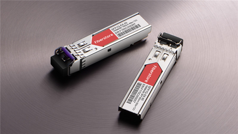
How many modules types do you know? From the Fiberstore, I find this answer.The Fiber Optic Transceivers have a full range of sfp modules. Fiberstore supply various kinds of SFP module 100% compatible with Cisco SFP, HP SFP, Juniper SFP, Netgear SFP, DELL SFP, CWDM SFP, DWDM SFP, BIDI SFP, 10G SFP and so on. Next, I will give you a brief introduction on SFP module types provided by Fiberstore.

SFP Module Types

First SFP Module Types: CWDM SFP

The CWDM SFP (small form-factor pluggable) transceiver is really a compact optical transceiver used in optical communications for both telecommunication and data communications applications on the wavelength. CWDM SFP are used to link the ports to the fiber optic network, typical CWDM SFP like Cisco’s could support both Gigabit Ethernet and Fiber Channel. CWDM SFP transceiver modules make use of the SFP interface for connecting the equipment and use dual LC PC fiber connector interface for connecting the optical network. FiberStore CWDM SFP transceivers can be found with a variety of different transmitter and receiver types, allowing users to decide on the appropriate transceiver for each link to provide the required optical reach over the available optical fiber.

Second SFP Module Types: DWDM SFP

The Dense Wavelength-Division Multiplexing (DWDM) transceivers offer DWDM transport with dramatically lower power and cost in a standard pluggable SFP package. Fiberstore DWDM SFP is available in all 100 GHz C/L-band wavelengths on the DWDM ITU grid. As multirate interfaces they support any protocol from 100 Mbps to 4.25 Gbps. The modules meet the requirements of the IEEE802.3 Gigabit Ethernet standard and ANSI Fiber Channel specifications, they are suitable for interconnections in Gigabit Ethernet and Fiber Channel environments. The DWDM SFP is designed to accept DWDM SONET/SDH (with or without FEC) for 200km links and Ethernet/Fiber Channel protocol traffic for 80km links.

Third SFP Module Types: 10G SFP

The 10G SFP Transceiver Modules refers to 10G SFP Plus Transceivers,someone know that the sfp+ is an enhanced version of the SFP that supports data rates up to 10 Gbit/s. Several standards for 10G SFP has been released, 10GBase-SR is for OM3 multimode optical fiber, relevant SFP plus working distance 300 meters max, 10GBase-LR is for single mode optical fiber, relevant SFP plus working distance 10km, 10GBase-LRM is for FDDI multimode fiber, the SFP plus working distance 220 meters.

Want to know more SFP Module Types, pls visit fs.com, We will continue to update fiber optic transceiver information.Our optical transceivers are backed by a lifetime warranty, and you can buy with confidence. We also can customize optical transceivers to fit your specific requirements.

Related Articles:

What Is The Difference: SFP vs SFP+

How Much Do You Know About SONET/SDH SFP Module?

How Many Types of SFP Transceivers Do You Know

Some Steps Of CCTV Installing And CCTV Tester

Share

CCTV(Closed-circuit television) uses one or more video cameras to send out video and sometimes audio images to a monitor, group of monitors, or video recorder. The real difference between CCTV and standard TV is the fact that standard TV openly broadcasts signals to the public. CCTV is not openly transmitted to the public. CCTV uses either wireless or wired transmission to send the broadcast from your cameras on the monitor or recorder. Most CCTV systems can be used surveillance, that may include security monitoring, spying, or safety monitoring. CCTV systems have become extremely popular over the past a long time since the technology has improved and be cheaper. Virtually all CCTV cameras being used today are generally for surveillance and security purposes. CCTV systems are available in nearly all bank, casino, mall, and big mall. CCTV systems have grown to be so affordable, most smaller mom and pop stores also have CCTV systems included for security purposes. To install a cctv in your life, you must have a cctv tester to testing the equipment, make sure the CCTV systems can work. Testing is very important to complete the project on agreed deadline and not to overspend or duplicate the work.

Install:

a. Ensure that the cables you might need to use is right.
b. Ensure that the cameras are in the correct location.
c. Ensure that you will find a proper reason for entrance externally of the house for the inside.
d. Find the best area for the screen and DVR to become stationed.
e. Find a sort of large capacity DC voltage because the energy with the CCTV video cameras.
f. After all the previous steps have being carried out, a appropriate CCTV security camera tester should be required.

Test:

The CCTV tester may be the useful gizmo for CCTV system, that is experiencing a leap in technology using digital techniques and also the Internet.CCTV tester can be used for displaying video, controlling PTZ, generating images, capturing data of RS485 and testing LAN cable etc. Its functions, easy operation, and convenient portability enable it simple for that contractor to set up and look after the playback quality camera, promote working efficiency and cost-down the expenditure from the project. .

Fiberstore is a professional fiber optic products supplier, you also can find other optical fibre products ethernet card, fiber switch, fiber optic connectors, etc. Welcome to our store to choose your fiber optic products.

Several Common Kinds of Fiber Optic Connectors

Share

Unlike Copper network cables, who have a standardized connector setup, fiber optic cables can employ many connector schemes to help make connections with patch panels, switch boxes, and the various fiber optic network implements that comprise a knowledge system.

Each of the different types of fiber optic connectors offers its advantages and disadvantages, and has its very own specific applications to which it’s best suited. Here’s a listing of one of the most common types of fiber optic connectors, their common uses, along with the advantages they can give your fiber optic network.

SC

Though there tend to be more types of fiber optic connector available on the market than can be adequately discussed here, the number of fiber optic connectors you’e planning to encounter inside a professional setting are relatively few. SC fiber optic connectors are probably the most common kinds of connector used for commercial purposes and realizing them will likely be needed for anyone using a fiber optic network.

The one outstanding good thing about SC fiber optic connectors is the snap-in design. This design lets them connect easily with other network implements. SC connectors have 2.5mm ferules and are well known for their reliable performance. Though they may be typically simplex (unidirectional) in nature, SC connectors with duplex (bidirectional) formatting can be purchased too.

SC connectors have widespread use within recent times, as a result of a welcome lowering of price. Ahead of this reduction, SC connectors were often subbed out for that less costly, though still technically impressive, ST connector.

ST

ST fiber optic connectors use a 2.5mm ceramic ferrule, including the SC fiber optic connector. However, whereas SC connectors mate using a snap-in mechanism, ST connectors work with a spring-loaded cinch to couple to network implements.

It is possible to typically find ST connector in older, large-scale multimode networks, such as those seen on business or academic campuses. The phrase multimode describes fiber optic cables which allow multiple propagation paths along which data can pass. ST connectors happen to be largely superseded about the consumer market by more modern connector schemes, nevertheless they can continue to deliver a satisfying performance for any large-scale network.

FC

Unlike the SC and ST connectors we merely discussed, FC fiber optic connectors are usually used with singlemode fiber optic cables offering one propagation path along which information can travel. Singlemode fiber optic cables are generally useful for cabling over longer distances than multimode fiber optic cables. Many datacom and telecom systems employ FC connectors for this specific purpose.

The FC fiber optic connector features a 2.5mm ceramic ferrule and effects its connections through a screw-type fasten.

LC

Which has a size only half those of the SC, ST, and FC fiber optic connectors, the LC fiber optic connector is a great option for cable terminations that must be effected quickly with little hassle. LC connectors possess a 1.25mm ceramic ferrule and provide reliable performance for singlemode fiber optic cables. Many pieces of communications technology that need high-density connections including SFP and XFP transceiver will employ LC fiber optic connectors.

MT-RJ

The MTRJ connector can be a somewhat different beast as opposed to connectors we discussed to date. The initials MTRJ stand for Mechanical Transfer Registered Jack. MTRJ connectors are designed to mimic the scale and type of the RJ-45 connectors typically that comes with the ends of Cat5, Cat5e, and Cat6 network cables.

With a single, polymer ferrule, MTRJ connectors are capable of making connections only with duplex, multimode fiber optic cables. Many adapters that will transfer data between a fiber optic network and a conventional, UTP data network, will employ MTRJ connectors because of their relative convenience.

Toslink

Much like the MTRJ connector, the Toslink connector serves a specialized purpose. Toslink connectors are some of the few fiber optic connectors intended almost only for the individual market. Sometimes referred to as optical audio connectors, Toslink connectors are prepared for carrying digital audio signals between audio sources and loudspeakers, via fiber optic cables.

The initial aim of the Toslink connector ended up being form connections between CD players and residential stereo systems. Today, Toslink connectors can be used connecting DVD players, Blu-Ray players, and computer game consoles to digital home theatre systems.

At fs.com obscurity is our obsession. Our passion to deliver large choice of Connectors. Find Fiber Connectors including SC, ST, FC, LC, MT-RJ, Toslink, plus much more!

4 steps in Fiber Optic Fusion splicer

Share

Fiber Optic Fusion splicer may be the act of joining two optical fibers end-to-end using heat. The thing is to fuse both the fibers together in such a way that light passing with the fibers is not scattered or reflected back from the splice, and thus the splice as well as the region surrounding it are almost as strong because virgin fiber itself. The basic fusion splicer apparatus includes two fixtures which the fibers are mounted and two electrodes. Inspection microscope assists in the placement in the prepared fiber ends into a fusion-splicing apparatus. The fibers they fit in to the apparatus, aligned, and then fused together. Initially, fusion splicing used nichrome wire as the heating unit to melt or fuse fibers together. New fusion-splicing techniques have replaced the nichrome wire with fractional co2 (CO2) lasers, electric arcs, or gas flames to heat the fiber ends, causing them to fuse together. The little size of the fusion splice along with the development of automated fusion-splicing machines make electric arc fusion (arc fusion) the most popular splicing approaches to commercial applications.

Splicing fiber optic cable ends together is often a precise process with hardly any room for error. This is because the optical fiber ends must be gathered absolutely perfectly to be able to minimize potential optical loss or light leakage. Properly splicing the cable ends demands the usage of a high-tech tool called a fusion splicer. A fusion splicer perfectly mates the optical fiber ends by melting or fusing them to the other. Splicing fiber cables surpasses using connectors considering that the fusing process results in a superior connection that features a lower level of optical loss. Now,I will introducts 4 steps to fusion splicing.

Step1

Know that fusion splicing is essentially several optical fibers being permanently joined together by welding utilizing an an electric arc. The need for an exact cleaver is suggested should you desire less light loss and reflection problems. Understand that an excellent cleaver just for this precise work is nessary. If your poor spice is created, the fiber ends may well not melt together properly and problems can arise.

Step2

Prepare the fiber by stripping the coatings, jackets and tubes, ensuring only bare fiber is left showing. You will need to clean all of the fibers associated with a filling gel. A clean environment is imperative for a good connection.

Step3

Cutter the fiber. A great wire cutter is suggested to secure a successful splice. When fusing the fibers together, either align the fibers manually or automatic, determined by what type of fusion splicer you’ve got. When you’ve got a new proper alignment, a power arc can be used to melt the fibers together creating a permanent weld of these two fiber ends.

Step4

Protect the fiber with heat shrink sleeve, silicone get. This can maintain your optical fiber resistant to any outside elements it may encounter or future breakage.

Alternatives to fusion splicing include using fiber optic connectors or mechanical splices because both versions have higher insertion losses, lower reliability far better return losses than fusion splicing. Want to know more about fiber splicer knowledges, pls visit fs.com to find your answer.

Some Types for GBIC Transceivers

Share

GBIC is short for gigabit interface converter, it is a media conversion device between Gigabit Ethernet and fiber optic networks, via the GBIC transceiver, Gigabit network equipment can directly connect to copper wires, single mode fiber ports or multimode fiber ports. The data transfer rate is one gigabit per second (1 Gbps) or more.

The Cisco® Gigabit Interface Converter (GBIC) is a hot-swappable input/output device that plugs into a Gigabit Ethernet port or slot, linking the port with the network. From FS.COM, we provide a full range of Cisco GBIC transceiver modules. There are many types for GBIC transceivers, such as Cisco WS-G5483,Cisco WS-G5484,Cisco WS-G5486,Cisco WS-G5487 and so on.

Cisco WS-G5483 (Copper) GBIC Transceiver

The Cisco WS-G5483 (1000BASE-T GBIC Transceiver) connects a GBIC port to Category 5 wiring using a standard RJ-45 interface. The maximum Category 5 wiring distance is 328 feet (100 m).Cisco WS-G5483, also called copper GBIC transceiver, is an ideal solution for Catalyst switch customers.

Cisco WS-G5484 (Short Wavelength) GBIC Transceiver

The Cisco WS-G5484 GBIC (1000BASE-SX GBIC Transceiver) operates on legacy multimode fiber (MMF) optic link spans up to 1804 feet (550 m) and on laser-optimized multimode fiber (OM3) optic link spans up to 3281 feet (1 km).The 1000BASE-SX is a short wavelength GBIC module.

Cisco WS-G5486 (Long Wavelength/Long Haul) GBIC Transceiver

The Cisco WS-G5486 (1000BASE-LX/LH GBIC Transceiver) fully complies with the IEEE 802.3z 1000BASE-LX10 standard. It allows for reaches up to 6.2 miles (10 km) over single-mode fiber (SMF) and up to 550 meters over multimode fiber (MMF). The long wavelength/long haul GBIC module is Cisco WS-G5486.

Cisco WS-G5487 (Extended Wavelength) GBIC Transceiver

The Cisco WS-G5487(1000BASE-ZX GBIC Transceiver) operates on ordinary single-mode fiber optic link spans up to 43.5 miles (70 km) long. Link spans of up to 62 miles (100 km) are possible using premium single-mode fiber or dispersion shifted single-mode fiber(premium single-mode fiber has a lower attenuation per unit length than ordinary single mode fiber; dispersion-shifted single-mode fiber has both lower attenuation and less dispersion). The GBIC provides an optical link budget of 21 dB – the precise link span length will depend on multiple factors such as fiber quality, number of splices, and connectors.

When shorter distances of single-mode fiber are used, it might be necessary to insert an in-line optical attenuator in the link to avoid overloading the receiver:

A 5-dB or 10-dB inline optical attenuator should be inserted between the fiber-optic cable plant and the receiving port on the Cisco 1000BASE-ZX GBIC at each end of the link whenever the fiber-optic cable span is less than 15.5 miles (25 km)

Note: The 1000BASE-ZX GBIC module provide an optical power budget of 21.5 dB. You should measure your cable plant with an optical loss test set to verify that the optical loss of the cable plant (including connectors and splices) is less than or equal to 21.5 dB. The optical loss measurement must be performed with a 1550-nm light source.

Function And knowledge With GBIC Transceiver Modules

Share

Gigabit Interface Converter referred to as GBIC, Gigabit convert electrical signals to optical signals interface device. GBIC transceiver is probably the many types of optical transceivers that will send and receive data. GBIC module is designed for hot-swappable. GBIC interchangeable products meet international standards. The GBIC interface design Gigabit switch interchangeable flexible to take into account a sizable market share available in the market.

GBIC module

Functions of GBIC Module

The GBIC transceiver functions being an input/output transceiver. It plugs into the gigabit Ethernet port on a single end, for instance a port found on network switching equipment. On the other end, the transceiver is attached to the fiber optic network, usually via fiber optic patch cords. The unit is seen as a features, including the wavelengths it can handle, how fast and efficiently it transmits data, the energy it needs to operate, and what distance it could transmit data over. These are the basic main considerations when purchasing a GBIC transceiver to make sure it meets network performance requirements.

Other important features of a GBIC transceiver which increase energy efficiency initiatives are how the unit offers low power dissipation and emits little electromagnetic interference. Each device can install and performance without disrupting anything, but this plug and play capability could be offset by the need to disconnect patch cords before it is installed or removed. Harmful electrical currents and data discrepancies can happen, and it is usually wise to take precautions to avert this whenever you can, specifically in high-density networks.

Transfer Speed of GBIC Module

Data rates vary on GBIC module model specifications, but they have a the least 1 gigabit per second. Manufacturers, such as Cisco, make GBIC modules with varying transfer speeds.

Signal Conversion of GBIC Module

The GBIC can be a module which is plugged into a device that generates electrical signals and in to a device that generates optical signals. The GBIC converts both signals backwards and forwards as needed by the devices. The GBIC even offers identification and system information which allows each device to learn the other’s capabilities.

Uses of GBIC Module

A GBIC module allows an individual to reconfigure fiber links, configure tailor receiver costs, link networking distances and organize network topologies based on set requirements. Utilized on a fiber optic or perhaps an Ethernet system, GBIC modules can be upgraded, substituted or plugged in without switching off the pc. This flexibility eliminates the need to replace entire system networking boards.

Many supplies sell GBIC transceivers. Fiberstore supply various kinds of GBIC module 100% compatible with Cisco GBIC Module, HP GBIC, 3COM GBIC, Netgear GBIC, Nortel GBIC, Extreme GBIC. CWDM GBIC, BIDI GBIC, Mini GBIC are also in stock.We not only supply the GBIC transceivers, but also have other fiber optic transceivers(for example, XENPAK modules, SFP modules, XFP module ).

Used The Crimping Tool To Made A RJ45 Plug

Share

The crimping tool is a tool designed to crimp or connect a connector to the end of a cable. For example, network cables and phone cables are created using a crimping tool to connect the RJ-45 and RJ-11 connectors to the end of the cable.At FiberStore,we supply some crimping tool to help you to made your need cable.So,I will tell you 9 steps to crimp a RJ45 Plug.

1, Stripping
The twisted pair twisted-pair wire stripper plastic sheath stripped of 2-3cm (Figure 1);
2, Winding Displacement
Untwist the paired wires and separate them. Then arranged the green line and the blue line in the middle position, and the orange line on the brown line on the outer position, the formation of the left orange, blue second from left, left Three Green, fourth from left brown line on the order (figure 2);
3, Cable Management
Carefully peel each line (open twist), and the line core T568B standard sort, especially to white and green cores from the blue and white blue line on the cross to the 3rd position, the line core straightened flatten, tight squeeze to straighten out (close to) in one direction (figure 3);
4, Cut
The the bare twisted-pair core pressure pliers, wire cutter, diagonal pliers and other tools neatly cut, leaving only about 13mm in length (figure 4);
5, Insert
Single-handedly crystal head, pinch the thumb and middle finger and index finger pointed at the direction of the crystal head metal pins facing up, shrapnel down. The other hand pinch the twisted pair, forced eight twisted pair wire sequence inserted into the crystal head slowly, and has been inserted into the top of the groove (figure5);
6, Check
Check the front of the crystal head to see the correct line sequence; Check crystal head top view 8 cores are the top to the top (figure 6);
7, Crimp
Checked and verified, the RJ45 Plug pushed into the pressure line clamp slot clenched crimping pliers, will be prominent on the outside of all the pressure pins crystal head into the RJ-45, RJ-45 crystal head connection is completed ( figure7-9).
8, Make A Patch Cable
Using the same standard install crystal head, the other side of the twisted pair to complete the production of direct access to the network jumper. The other side of the T568A standard installation crystal head, completed a crossover cable production.
9, Test
With a simple line in the training stage of the test device or toolbox integrated wiring sequence tester to test the network, there will be through straight-through cable crossover cable by open circuit, short circuit, reverse polarity, jumper display results. RJ-45 crystal head protective pouches prevent jumper pulled cause poor contact before you connect RJ-45 crystal head, crystal head To use this pouches, need pouches inserted in the twisted-pair cable, the connection then put pouches.

Note:
1,Stripping can not cut through the insulation of the twisted pair wires;
2, pay attention to the pressure line intensity should be moderate

Learning this article to know how to crimp a RJ45 Plug and some note,do you want to Crimping your own RJ45 plugs will allow you to create cable lengths specific to your needs. Hurry up to FiberStore to buy the tool and cable to try,our product always has a high quality and low price.

The Detail For RJ45 Interface Connector

Share

In this network era, the connector has been becoming more and more popular in our life. All kinds of copper wires and fiber optic cables are likely to require corresponding connectors such as RJ45 connectors/plugs and fiber connectors. Here, we focus on the connector for RJ45 Interface involved with RJ45 Ethernet cable.

What Is RJ45 Interface Connector?

Commonly known as “crystal head” given its appearance, RJ45 interface connector is a kind of component that can insert along a fixed direction into a RJ45 interface and can prevent loss of plastic connectors automatically. RJ45 is a kind of network interface specification (similar to RJ11 interface, commonly used as “telephone interface” to connect telephone lines). Crystal head is suitable for the equipment or horizontal subsystem field termination, shell material with high density polyethylene. Both ends of the twisted pair must be installed RJ45 plug to plug the RJ45 connector on the RJ45 interface card (NIC), the hub or switch on RJ45 interface, for network communication. Each of the twisted pair at both ends by installing crystal head with NIC connected to a hub (or switch). RJ45 interface is typically used for data transmission, the most common application interfaces for the network card.

RJ45 Interface Connector

Line Sequence for Network Cable Cords

The RJ45 network cord, made up of a total of eight core, is widely used in LAN and ADSL broadband Internet between network devices for network cable connection. It is often inserted into a RJ45 interface connector to form a RJ45 Ethernet cable.

There are two connection orders  (line sequence) for the eight cores. Normally, the two line sequence were referred to as T568A line order and T568B wire order in the specific application. One order for T568A is white green, green, white orange, blue, white blue, orange, white brown, brown; the other is white orange, orange, white green, blue, white blue, green, white brown, brown.

T-568A-vs.-T-568B

RJ45 Interface Connector Types

Common RJ45 connector can be divided into two categories: DTE type used in Ethernet card, router, etc., and the DCE type used in switches, etc. DTE is called “data terminal equipment”, DCE is known as “data communications equipment”. In a sense, DTE device known as the “active communication equipment”, DCE devices referred to as “passive communication equipment”. When two types of devices using RJ45 interface connection communication, one must use a crossover cable connection.

Conclusion

In network products, network cable and RJ45 connector may be ordinary but necessary. Although Internet cable and crystal head is not important things, but if the quality of cable with crystal head is not good, then you will often meet all kinds of puzzling problem when surfing the Internet for transmission and the exchange of important data. So the choice and buying of cables and crystal head is important as well. By the way, FS.COM offers RJ45 Plugs with high quality and have superior performance in your networking system.

Related Articles:
How to Choose and Buy the Best Ethernet Cable
Difference of Straight Through and Crossover Cable
Patch Cable vs. Crossover Cable: What Is the Difference?
Quick View of Ethernet Cables Cat5, Cat5e And Cat6