Monthly Archives: March 2015

What’s Difference Between CFP and CXP Transceivers?

Share

Two years ago, though everyone is talking about the 100G Ethernet as the next generation, it had still faced a lot of problems to be solved, seeming to be a long way off. But, technologies are developed very rapidly, and now 100G Ethernet is becoming more and more closer to us. Fiber connectivity in higher-speed active equipment is being condensed and simplified with plug-and-play, hot-swap transceiver miniaturization. Thus, optical transceiver technology is one of the basic but important technology to achieve the realiable and effective 100G Ethernet. Interfaces for 100G active equipment include CFP and CXP. So, what are CFP and CXP? And what’s the difference between CFP and CXP? Is CXP transceiver designed to replace the CFP? … You might be interested in them and have a lot of questions in your mind. Today, you will find the answer in this post.

About CFP
cfp-100g85-1m-ju-01
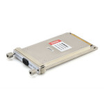
CFP, short for C form-factor pluggable, is a multi-source agreement to produce a common form-factor for the transmission of high-speed digital signals. The c stands for the Latin letter C used to express the number 100 (centum), since the standard was primarily developed for 100 Gigabit Ethernet systems. In fact, CFP also supports the 40GbE. When talking about CFP, we always define it as multipurpose CFP, compared to the CXP which is discussed later.

The CFP MSA was formally launched at OFC/NFOEC 2009 in March by founding members Finisar, Opnext, and Sumitomo/ExceLight. The CFP form factor, as detailed in the MSA, supports both single-mode and multi-mode fiber and a variety of data rates, protocols, and link lengths, including all the physical media-dependent (PMD) interfaces encompassed in the IEEE 802.3ba standard. At 40GE, target optical interfaces include the 40GBase-SR4 for 100 meters (m) and the 40GBase-LR4 for 10 kilometers (km). There are three PMDs for 100 GE: 100GBase-SR10 for 100 m, 100GBase-LR4 for 10 km, and 100GBase-ER4 for 40 km.

CFP was designed after the Small Form-factor Pluggable transceiver (SFP) interface, but is significantly larger to support 100Gbps. The electrical connection of a CFP uses 10 x 10Gbps lanes in each direction (RX, TX). The optical connection can support both 10 x 10Gbps and 4 x 25Gbps variants. CFP transceivers can support a single 100Gbps signal like 100GE or OTU4 or one or more 40Gbps signals like 40GE, OTU3, or STM-256/OC-768.

The CFP-MSA Committee has defined three form factors:

  • CFP – Currently at standard revision 1.4 and is widely available in the market
  • CFP2 – Currently at draft revision 0.3 is half the size of the CFP transceiver; these are recently available in the market
  • CFP4 – Standard is not yet available, is half the size of a CFP2 transceiver, not yet available

CFP transceiver today to future

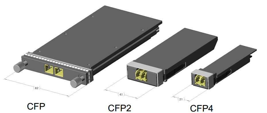
The original CFP specification was proposed at a time when 10Gbps signals were far more achievable than 25Gbps signals. As such to achieve 100Gbps line rate, the most affordable solution was based on 10 lanes of 10Gbps. However as expected, improvements in technology has allowed higher performance and higher density. Hence the development of the CFP2 and CFP4 specifications. While electrical similar, they specify a form-factor of 1/2 and 1/4 respectively in size of the original specification. Note that CFP, CFP2 and CFP4 modules are not interchangable (but would be interoperable at the optical interface with approriate connectors).

About CXP
CXP
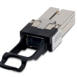
CXP is targeted at the clustering and high-speed computing markets, so we usually called it high-density CXP. Technically, the CFP will work with multimode fiber for short-reach applications, but it is not really optimized in size for the multimode fiber market, most notably because the multimode fiber market requires high faceplate density. The CXP was created to satisfy the high-density requirements of the data center, targeting parallel interconnections for 12x QDR InfiniBand (120 Gbps), 100 GbE, and proprietary links between systems collocated in the same facility. The InfiniBand Trade Association is currently standardizing the CXP.

The CXP is 45 mm in length and 27 mm in width, making it slightly larger than an XFP. It includes 12 transmit and 12 receive channels in its compact package. This is achieved via a connector configuration similar to that of the CFP. For perspective, the CXP enables a front panel density that is greater than that of an SFP+ running at 10 Gbps.

Typical applications of CXP in the data center include 100GE over Copper (CXP): 7m (23ft) and 100GE over multimode fiber: CXP for short reach applications (CFP is used for longer reach applications).

What’s the Difference Between CFP and CXP?
Despite having a similar acronym and emerging at roughly the same time, the CFP and CXP form factors are markedly different in terms of size, density, and intended application. The CFP and CXP optical transceiver form factors are hot pluggable, both feature transmit and receive functions, and both support data rates of 40 and 100 Gbps. But the similarities begin and end there. Aimed primarily at 40- and 100-Gigabit Ethernet (GbE) applications, the CFP supports both singlemode and multimode fiber and can accommodate a host of data rates, protocols, and link lengths. The CXP, by contrast, is targeted at the clustering and high-speed computing markets. The two are therefore complementary, not competitive, according to several sources. Thus, the existence of CXP does not mean the replacing of CFP.

However, things are never black and white. In some case, there is a competition between CFP and CXP, as CFP can also be used with multimode fiber. It becomes more of a choice for system vendors. Do they need to build a box that can adapt to any interface? If so, they would probably use CFP. If it’s a box that is just focused on the short-reach market, then they would probably use something more like CXP.

I hope this post will let you more understanding the 100GbE transceivers, whether CFP or CXP. Similarly, you could kown the 40GbE transceiver through this post as the CFP and CXP also support the 40GbE. If you want to have a further study on this subject, I suggest you to learn the related refference of MSA.

Article Source: http://www.fiber-optic-transceiver-module.com/whats-difference-between-cfp-and-cxp-transceivers.html

Ultra-High-Power Optical Amplifier for FTTH – EYDFA

Share

Background

While the Cable Modem, xDSL, and other forms of broadband access are booming in recent years, Fiber To The Home (FTTH) access is also gradually becoming a project that people are very interested in. The FTTH will eventually realize the “three networks in one” of Telephone, CATV and Internet, when the speed of data transmission can be more than 100 Mbps (200 times faster than the commonly used dial-up Internet access) and bring homes high-definition TV movies and fast online office, etc. FTTH can also solve the problem such as the quality of phone calls, the definition of television and so on.

From the perspective of the world’s situation, the FTTH’s promotion of South Korea and Japan has entered a rapid growth period; North America and Europe has begun to start which brings an optimistic outlook; China, Russia, India and South America is following and speeding up the development. From the perspective of FTTH, the optical communications industry market’s growth potential is still very large.

Applications of High-Power Optical Amplifiers

High-power optical amplifier as one of the basic devices of modern optical communications, is not only the premise of the existence of large-capacity and long-distance all-optical communication networks, but also plays a more and more important role in the process of fiber optic networks’ constantly extending and expanding. At present, in the central office, it usually needs to install more than one optical amplifiers in order to cover larger scope and more users. To take CATV for example, if a medium-sized county needs to send high-quality first-level TV signals to the villages and towns, it generally needs 4 to 8 sets of optical amplifiers. However, if high-power optical amplifiers are used, then only one is enough, which can greatly reduce the cost.

Solutions of High-Power Optical Amplifiers

Traditional Solution using EDFA Technology

One of the solutions for high-power optical amplifiers is to use the traditional general EDFA technology. As shown in the figure below, the signal is amplified at the first stage and then divided into several parts into several EDFAs at the second stage to realize the further ascension of power. The power enlarged in the end can be allocated.

Traditional High-Power Solution using EDFAs

Theare are mainly four problems of this solution:

  • The adoption of multilevel structure will make the optical structure very complex, and due to the adoption of multiple lasers in the internal part, the corresponding control scheme is very complicated.
  • As the multilevel structure has a WDM between the two stages of optical amplifiers, equivalent to bring more insertion loss to the optical path, the noise figure of EDFA amplifiers will deteriorate.
  • In addition, the traditional EDFAs use single mode fiber core pump technology, but high-power single-mode pumped lasers have been greatly restricted on technical and cost.
  • The whole sets of EDFA’s cost is very high and is very expensive.

Better Solution using EYDFA Technology

This ultra-high-power amplifier technology is a multimode cladding pump technology—EYDFA technology, a recently developed new technology that uses the Yb3+ and Er3+ ions doped double-clad fiber. The technology results to the combination of a series of new technologies, new processes and new materials. It is the core technology of ultra-high-power amplifiers and represents the development direction of optical amplifier technologies. While traditional EDFA use single-mode fiber core pump technology to achieve higher output power (which has been greatly limited on the technical and cost), the Er/Yb-Doped Fiber Amplifier (EYDFA) multimode cladding pump technology is the best choice for large output power optical amplifiers. Here is a typical optical structure of EYDFA.

EYDFA Structure

The main advantages of EYDFA are as following:

  • Compared with the single mode fiber core pump technology, multimode cladding pump technology has obvious advantages. The multimode cladding pump technology is to input the pump light to the multimode double-cladding fiber whose cross section are hundreds to thousands of times the single-mode fiber. As a result, at the same input optical density, multimode cladding pump can allow hundreds to thousands of times the single-mode pumped input, easily realizing the optical amplifiers’ high output power or ultra-high output power.
  • Can be realized using a simple optical structure, so the application form is very simple (as shown in the figure below).EYDFA Application Structure
  • The overall cost of the pumps can be greatly reduced.

Fiberstore’s high-power optical amplifier module type products—FTTH-EYDFA series are featured with high output power (17–26 dBm), low noise figure (less than 6 dB @ 1550 nm, 5 dBm input power), wide range of working wavelength (1540–1565 nm), flexible control, high reliability, etc. The output power of high-power optical amplifier is nearing 32 dBm in the laboratory.

Conclusion

Predictably, the widely applications of the ultra-high-power optical amplifiers (EYDFA) will have a profound impact on the development of optical communication, and its market prospect and effectiveness to economic and social present a good trend.

Cable Selection for Your 10 Gbps Transmissions — Fiber or Copper?

Share

The decision to deploy fiber or copper really depends on several factors. First is the length of time you think the data center will remain in the same physical location. Fiber-only or copper-only implementations are rare in comparison to mixed fiber and copper.

Fiber will remain the medium of choice for backbone (vertical) applications and increasingly for horizontal applications alongside copper. This is mainly due to the distance support, size of cable, high bandwidth, high density, immunity to EMI/RFI, security, and reliability of fiber. Fiber has been the medium of choice for Storage Area Network (SAN) implementations for many years and is thus a proven cabling component.

Structured Cabling

Copper, on the other hand, is currently being challenged with the recent ratification of 10GBASE-T. Companies are currently racing to market their “unique” copper-based structured cabling solutions for 10 Gbps devices. Cat6a copper cables made for 10 Gbps transmissions are approximately 50 percent thicker than Cat6 copper cables and certainly a lot thicker than fiber cables; the space available for the cable runs may influence the type of cable you deploy. Copper cabling is more suited for horizontal runs, but of course limited to 100 meters distance. It is advisable to install a higher category of cable if you plan to be at the same facility for a while.

Cat6 CablesCat6 Cables Cat6a CablesCat6a Cables

Until recently, copper was the clear winner in a straight cost comparsion. However, recent technology advances are closing the cost gap, especially in the high-performance arena. Fiber-based solutions are dropping in cost, but the main differentiation is in the cost of the active electronic components (e.g. transceivers, converters, amplifiers, etc.), and not in the actual cabling. In parallel, the cost for copper-based solutions is on the rise, due primarily to the stringent implementation and testing requirements imposed by TIA/ISO for 10 Gbps transmissions. Note also that in support of “Greener” data center environments, certain vendors are choosing, designing, and promoting active cabling components and media that consume the least power without compromising performance. 10GBASE-T consumes about 5 to 10 times more electrical power than optical solutions.

Another area that plays an important role in cable selection is the network components that are planned in the data center. Is their interface fiber or copper? And do they support 10 Gbps transmissions? Upgrading the cabling may include swapping out the connectors and other existing cabling components for the ones slated for 10 Gbps.

Note: If you want to deploy Power over Ethernet (PoE), then your choice is limited to copper—carring power over fiber is not yet possible.

Conclusion

In most cases, the end result will be a Combination of Cable Types for the Different Segments of the Infrastructure. Most likely fiber for the backbone, fiber and/or twisted pair for the horizontal runs, and fiber and/or copper for the final patching (since this will be governed by the interface of the equipment that you will be connecting to). When selecting cableing consider the pros and cons for each cable type in each segment of the infrastructure using the following criteria:

    • Existing implementation
    • Installation difficulty
    • Termination difficulty
    • Reliability
    • Distance required
    • Compatibility

Wavelength Selective Couplers and Splitters

Share

Wavelength Selective Couplers (or Splitters) are used to either combine or split light of different wavelengths with minimal loss. Light of two different wavelengths on different input fibers can be merged (combined) onto the same output fiber. In the reverse direction light of two different wavelengths on the same fiber can be split so that one wavelength goes to one output fiber and the other wavelength is output onto the other output fiber. The process can be performed with very little loss.

As the coupling length is wavelength dependent, the shifting of power between the two parallel waveguides will take place at different places along the coupler for different wavelengths. All we need to do is choose the coupling length carefully and we can arrange for loss free wavelength combining or splitting. These functions are shown in the figure below. The graph of power transfer shows how power input on one of the fibers shifts back and forth between the two waveguides. The period of the shift is different for the two different wavelengths. Thus in the left-hand section of the diagram (combining wavelengths) there will be a place down the coupler where all of the light is in only one waveguide. If we make the coupler exactly this length then the signals have been combined. On the right-hand side of the diagram the reverse process is shown where two different wavelengths arrive on the same input fiber. At a particular point down the coupler the wavelengths will be in different waveguides so if we make this the coupling length then we have separated the wavelengths exactly. In fact both the processes described above are performed in the same coupler—the process is Bi-Directional (BiDi). Thus the coupler on the left can operate in the opposite direction and become a splitter and the splitter on the right can operate in the opposite direction and become a coupler (combiner). Note that each coupler or splitter must be designed for the particular wavelengths to be used.

Wavelength Selective Coupling and Splitting

Commercial devices of this kind are commonly available and are very efficient. The quoted insertion loss is usually between 1.2 and 1.5 dB and the channel separation is quoted as better than 40 dB. “Wavelength flattened” couplers or splitters of this kind operate over quite a wide band of wavelengths. That is a given device may allow input over a range of wavelengths in the 1310 nm band up to 50 nm wide and a range of wavelengths in the 1550 nm band also up to 50 nm wide.

Power Input to an EDFA

On the left-hand side of the figure we see an example of coupling two different wavelengths into the same output fiber. At the input of an EDFA you want to mix the (low level) incoming signal light with (high level) light from the pump. Typically the signal light will be around 1550 nm and the pump will be 980 nm. In this case it is possible to choose a coupling length such that 100% of the signal light and 100% of the pump light leaves on the same fiber. A major advantage of this is that there is very little loss of signal power in this process.

Splitting Wavelengths for CWDM Systems

On the right-hand side of the figure we show an example of CWDM demultiplexing. A mixed wavelength stream with one signal in each of the 1300 and 1550 nm bands is separated into its two component wavelengths. A CWDM system like this might be used in a system for distributing CATV and advanced VOD services to people in their homes. One signal stream might be carried at 1310 nm and the other at 1550 nm. A resonant coupler is shown here operating as a splitter separating the two wavelengths. Note that an identical splitter could also be used to combine the two wavelengths with very little loss.

Adding the Management Channel in DWDM Systems

In DWDM systems where many channels are carried in the 1550 nm band there is often a requirement to carry an additional relatively slow rate channel for management purposes. A convenient way to do this is to send the management information in the 1310 nm band and the mixed DWDM stream in the 1550 band. Wavelength selective couplers are commonly used for this purpose. A management signal (a single wavelength) in the 1310 band is coupled onto a fiber carrying many wavelengths between 1540 nm and 1560 nm. Another similar device (wavelength selective splitter) is used to separate the signals at the other end of the link.

Article Source: http://www.fiberopticshare.com/wavelength-selective-couplers-and-splitters.html