Monthly Archives: October 2014

Punch-Down Block and Patch Panel

Share

The cable runs in a structured cabling environment terminate in a punch-down block, which is usually a 66-block or a 110-block, or BIX- or Krone-style blocks, “Cabling System Connections and Termination.” The 110-block is most commonly used for voice and data cabling termination, although you will find many installations that use a 110-block for termination voice systems and patch panel for terminating data systems. Punch-down block termination provides a cross-connect from one cable set to another, allowing for easier moves, adds, and changes (MACs) as the need arises.

What Is A Punch-Down Block?

A punch-down block is mounted to a backboard, which is usually made of plywood and secured to the wall of a TC. If you install cabling on more than the floor, each floor must have a separate punch-down block with terminations for the cable drops from the higher floors. Backbone cables should be installed with 10-foot service coils at the termination points, which are commonly located on the backboard in the closet. Figure 1 illustrates a typical TC.

Install patch cables from the punch-down block to a patch panel. The purpose of the patch panel is to connect the backbone system to networking equipment such as a hub or router. End-user equipment, which includes workstations, network printers and scanners, and other shared electronic equipment, generally connect to a hub (also called a concentrator) or router via RJ-45 cable jacks or outlets.

There are pros and cons to using cross-connect blocks. They offer higher densities and require less space than patch panels, and also are less expensive. On the other hand, they are the least friendly for making moves, adds, and changes to the configuration. Skill is involved in removing and rea-ranging cables. When using patch panels, almost anyone can rearrange the system. In both situations security, ease of attachment, expense, and physical space are all considerations.

What Is Fiber Optic Patch Panel?

Fiber optic patch panel is commonly used in fiber optic management unit. When you install and manage the fiber optic links, you may encounter hundreds or even thousands of fiber optic cables and cable connections, fiber optic management products are used to offer space and protection for the fiber cables and cable links, and they make it easier for the cable management and troubleshoot work. Our fiber optic patch panels are all sliding type, they are compatible to use with equipment and cable assembly products from other companies. Now you can see the two products from our store. They are SC fiber patch panel, 24 Port Fiber Patch Panel.

12 port  OS1/2 9μm Duplex Plastic SC Fiber Patch Panel

Features of FS001 SERIES MOLDED

● Compatible with Leviton fiber adapter panels
● Adapter panels offered in LC, SC, ST, and blank styles, fit for all Opt-X rack-mount and wall-mount enclosures and VertiGO® panels
● Equipped with plastic dust caps to make connecting panels tool-free and efficient
● Integrated couplers eliminate “rattle” and loose fit
● Captive push-lock pins allow for quick tool-less installationCaptive push-lock pins allow for quick tool-less installation
● Exceeds optical performance standards and meets all other applicable standards

12 pack LC Duplex 24 Port Fiber Patch Panel Blue

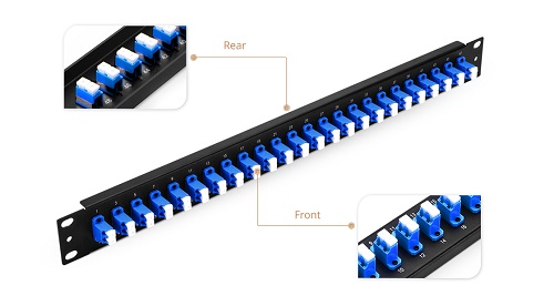
24 port Patch Panel

● Compatible with BlackBox Fiber Adapter Panel
● Adapter panels snap easily into all standard fiber enclosures, cabinets, and patch panels, including all Black Box® models.
● High-density panels with ST or LC connectors are available.
● The easy way to patch fiber cables to termination enclosures

We supply many fiber optic patch panels. They are with types to fit from 12 fibers to 72 fiber management demand. These fiber optic patch panels are with optional various kinds of fiber optic adapters and fiber optic pigtails, types including SC, LC, ST, FC, MU, E2000, etc.  We have a number of different customizable options available to fit whatever application you require. With products compatible with trusted brands including Black Box, Wirewerks, Mr-technologies, Corning, Leviton, Panduit Opticom adapter panel and more.

Fiber Optic Enclosures In Cabling Systems

Share

Overview of Fiber Optic Enclosures

Just like copper-based cabling systems, fiber-optic cabling systems have a few specialized components, including fiber optic enclosures and connectors.

Because laser light is dangerous, the ends of every fiber-optic cable must be encased in some kind of fiber optic enclosure. The fiber optic enclosure not only protects humans from laser light but also protects the fiber from damage. Wall plates and patch panels are the two main types of fiber optic enclosures. We’ll discuss patch panels here.

When most people think about a fiber optic enclosure, a fiber patch panel comes to mind. It allows connections between different devices to be made and broken at the will of the network administrator. Basically, a bunch of fiber-optic cables will terminate in a patch panel. Then, short fiber-optic patch or interconnect cables are used to make connections between the various cables. There are dust caps on all the fiber-optic ports, which can prevent dust from getting into the connector and interfering with a proper connection.

Types of Fiber Optic Enclosures

Patch panels come in many shapes and sizes. Some are mounted on a wall and are known as surface-mount patch panels. Others are mounted in a rack and are called rack mount patch panels. Each type has its own benefits. Surface mount panels are cheaper and easier to work with, but they can’t hold as many cables and ports. Surface-mount patch panels make good choices for smaller (fewer than 50 drops) cabling installation. Rack-mount panels are more flexible, but they are more expensive. Rack mount patch panels make better choices for larger installations. Patch panels are the main products used in LAN installations today because they are extremely cost-effective and allow great flexibility when connecting workstations.

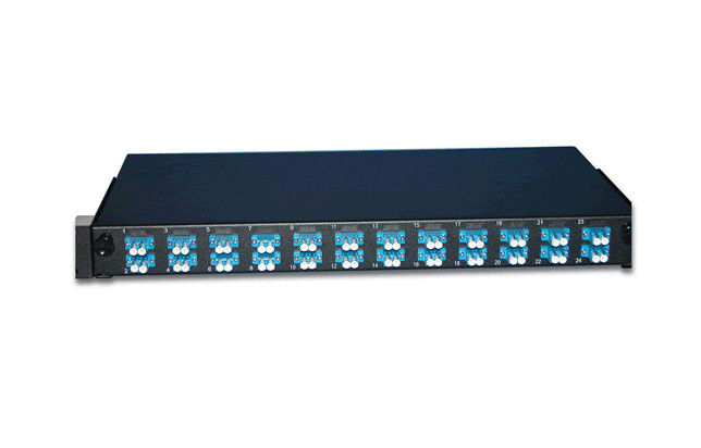
In addition to the standard fiber patch panels, a fiber-optic installation may have one or more fiber distribution panels, which are very similar to patch panels in that many cables interconnect them. However, in a distribution panel, the connections are more permanent. Distributions panels usually have a lock and key to prevent end users from making unauthorized changes. Generally speaking, a patch panel is found wherever fiber optic equipment hubs, switches, and routers are found. Distribution panels are found wherever multifiber cables are split out into individual cables. Here is the example of 24 port patch panel.

24 port patch panel

Our wall mounted fiber optic enclosures accommodate up to 8 modular panels and is equipped with routing guides to limit bend radius and enhance strain-relief control. The 16-gauge steel with corrosion-resistant black powder finish coat housing provides excellent protection for the inside fibers. Wall-mount available unloaded, as well as having the capability to become a full-splice enclosure with mechanical terminations. A large variety of connector adapters are offered to meet your specific requirements. Such as SC, FC, ST, LC, etc, we can also pre-install various kinds of fiber optic pigtails inside the patch panel. We offer a series of changeable inside panels to fit for different kinds of the adaptor interface, and fit for both round and ribbon fiber optic cables.

Some Knoweledge About Erbium-droped Fiber Amplifer

Share

The eribum-doped fiber amplifier (EDFA) was first reported in 1987, and, in the short period since then, its applications have transformed the optical communications industry. Before the advent of optical amplifers, optical transmission systems typically consisted of a digital transmitter and a receivere separated by spans of transmission optical fiber intersersed with optoelectronic regenerators. The optoelectronic regenerators corrected attenuation, dispersion, and other transmission degradations of the optical signal by detecting the attenuated and distorted data pulses, electronically reconstituting them, and then optically transmitting the regenerated data into the next transmission span.

The EDFA is an optical amplifer that faithfully amplifies lightwave signals purely in the optical domain. EDFAs have several potential functions in optical fiber transmission systems. They can be used as power amplifiers to boost transmitter power, as repeaters or in-line amplifiers to increase system reach, or as preamplifiers to enhance receiver sensitivity. The most far-reaching impact of EDFAs has resulted from their use as repeaters in place of conventional optoelectronic regenerators to compensate for transmission loss and extend the span between digital terminals. Used as a repeater, the optical amplifier offers the possibility of transforming the optical transmission line into a transparent optical pipeline that will support signals independent of their modulation format or their channel data rate. Additionally, optical amplifiers support the use of wavelenth division multiplexing (WDM), whereby signals of different wavelengths are combined and transmitted together on the same transmission fiber.

In fiber optic systems amplification of the signal is necessary because no fiber material is absolutely transparent. This causes the infrared light (usually around 1530nm) carried by a fiber to be attenuated as it travels through the material. Because of this attenuation, repeaters must be used in spans of optical fiber longer than approximately 100 kilometers.

The operating wavelength range of a standard EDFA spans over the entire so-called “C band” (1530 to 1560 nm) and therefore allows amplification of a variety of wavelength channels that are used in wave-length division multiplexing (WDM)applications. This is a major advantage over methods in which the optical signal is converted into an electrical signal, amplified and converted back to light. Due to the last step, such O/E-E/O regenerators require the demultiplexing and multiplexing of each single WDM channel at each regenerator site and an O/E-E/O pair for each channel.

EDFA Configurations

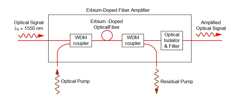
The configuration of a co-propagating EDFA is shown in Figure 5. The optical pump is combined with the optical signal into the erbium-doped fiber with a wavelength division multiplexer. A second multiplexer removes residual pump light from the fiber. An in-line optical filter provides additional insurance that pump light does not reach the output of the optical amplifiers. An optical isolator is used to prevent reflected light from other portions of the optical system from entering the amplifier.

fiber optic amplifer

Figure 5. An EDFA for which the optical signal and optical pump are co-propagating.

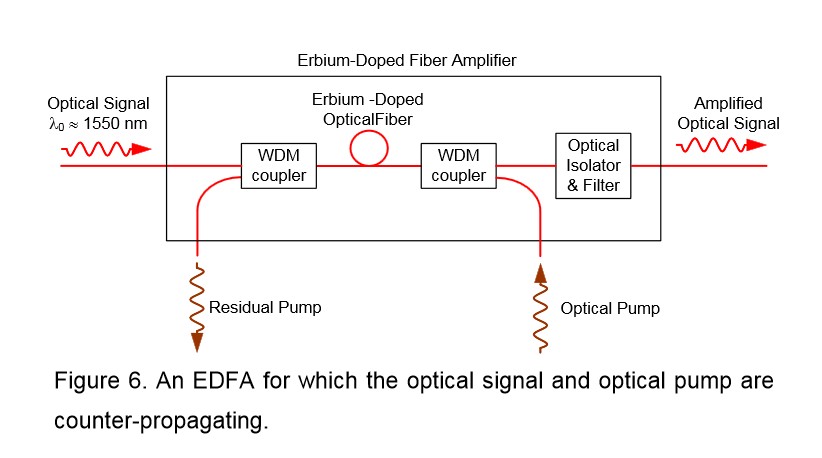
An EDFA with a counter propagating pump is pictured in Figure 6. The co-propagating geometry produces an amplifier with less noise and less output power. The counter propagating geometry produces a noisier amplifier with high output power. A compromise can be made by combining the co- and counter-propagating geometries in a bi-directional configuration.

EDFA Amplifer

The propagation and amplification properties of an erbium-doped fiber at 1550 nm are obtained. A simple EDFA is constructed, and its performance is tested. A small signal with wavelength of 1530 nm can be amplified with amplification up to 14 dB/m and SNR of 18.8, if a pumping laser of wavelength 980 nm and driving current 400 mA is used. A higher amplification is expected if a more intense pumping laser is supplied. The erbium doped fiber amplifier proves efficient and concise in amplifying signals around 1550 nm.

FBG Sensor Multiplexing Techniques On WDM System

Share

Fiber Bragg Grating (FBG) is a simple and low-cost filter built into the core of a wavelength-specific fiber cable. FBGs are used as inline optical filters to block certain wavelengths, or as wavelength-specific reflectors.

In many applications a large number of sensors need to be used to achieve a distributed measurement of the parameters. In particular, using sensors in smart structures is of interest where sensor arrays are bonded or embedded into the materials to monitor the health of the structure. FBG sensors have a distinct advantage over other sensors because they are simple, intrinsic sensing elements that can be written into a fiber, and many sensors can be interrogated through a single fiber.

The most straightforward multiplexing technique for FBG sensors is wavelength division multiplexing (WDM), utilizing the wavelength-encording feature of an FBG-based sensor. The WDM technique is based on spectral splicing of an available source specturm. Each FBG sensor can be encoded with a unique wavelength along a single fiber. Since we are operating in the wavelength domain, the physical spacing between FBG sensors can be as short as desired to give accurate distributed information of measurands.

A parallel topology is used to allow simultaneous interrogation of all the sensors in WDM, as shown in Figure 4.15. A1 x N fiber optic splitter is used to divide the optical reflection into N channels, In each channel a matched fiber grating detects the wavelength shift from a specific FBG sensor.

Fiber splitter

In the parallel scheme each filter receives less than 1/2N of optical power as a result of using 1 x N fiber splitter and fiber coupler. More FBG sensors lead to a larger power penalty. An improved scheme using a serial matched FBG array is reported by Brady et al, as shown in Figure 4.15(b). This scheme is claimed to allow the optical power to be used more efficently than in the parallel topology. As can be seen, however, a large power penalty still exists through the use of the reflection of matched fiber gratings. A revised verison of the serial scheme is proposed, in which the transmisson of the matched FBG is used to monitor the wavelength shift from the corresponding sensing FBG. This reduces the power penalty of 6 dB.