How Much Do You Know About QSFP56?

Share

Over the past years, there have emerged various optical module form factor types with the growth of new technology and high-speed interconnects, among which QSFP56, as a member of the QSFP family, is a solution for 200G applications. What‘s the difference between QSFP56 with other QSFP family form factors? Is QSFP56 the same as QSFP56-DD? If you are wondering about these questions, this article is for you.

Figure 1: Transceiver form factor

QSFP56—Form Factor of 200G Transceivers

To make clear what QSFP56 is, let’s take a look at the QSFP form factor first. Quad Small Form-Factor Pluggable (QSFP) was developed after SFP, which was originally designed to replace the single-channel SFPs with high-density optical modules. Due to the fact that it denotes four lanes for up to 4 wavelengths, it provides higher bandwidth capacity compared with the SFP modules.

Developed on the basis of QSFP, 40G QSFP+ arose and then 100G QSFP28 came into use for high-density applications. With the rising of data traffic in data centers and advanced network applications, the market is urgent to achieve higher-speed general availability. There is more addition to QSFP family form factors, such as 200G QSFP56 and 400G QSFP56-DD.

Figure 2:Types of QSFP form factor

As an evolution of the previous 40G QSFP+ and 100G QSFP28, Quad 50 Gigabits Small Form-factor Pluggable (QSFP56) is the one designed for 200G Ethernet. QSFP56 denotes 4 x 50 to 56Gb/s in a QSFP form factor. Sometimes it can also be referred to as 200G QSFP for sake of simplicity. QSFP56 optical modules are similar to QSFP ones in terms of size and form factor. Classified by distance, QSFP56 modules can be divided into QSFP56 CR, SR, DR, FR, LR, which enables different transmission distances over a single mode fiber (SMF) or multimode fiber (MMF).

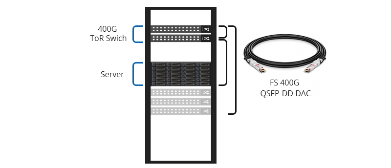
Generally, two QSFP56 modules can be used with an SMF or MMF to realize a 200G link. QSFP56 AOC/DAC is also a way to realize a 200G link by connecting QSFP56 ports on two devices in a simplified linking process. For bridging 200G QSFP56 ports with other speeds, there are 200G QSFP56 to 2x100G QSFP28 breakout cables and 200G QSFP56 to 4x50G SFP56 breakout cables to achieve 2x100G or 4x50G connections.

QSFP56 vs QSFP28 vs QSFP+

Seen from their industry names, QSFP56, QSFP28 and QSFP+ are very similar in that they share the same QSFP form factor as their postfix shows, and they have the same size as each other. However, their data center and connectivity capabilities are different. Below is a table listing the basic parameters of QSFP56, QSFP28, and QSFP+.

Industry nameYearoriginal meaningNumber of Electric LanesNumber of Optical LanesBit Rate/LaneModulationLine Rates
QSFP+2013Quad Small Form-factor Pluggable Plus4410GbpsNRZ40G
QSFP282016Quad Small Form-factor Pluggable 284425GbpsNRZ100G
QSFP562017Quad 50 Gigabits Small Form-factor Pluggable4450GbpsPAM4200G

From the comparison chart, it can be distinctly seen that compared with QSFP+ and QSFP28, the QSFP56 form factor performs a higher network speed as 200G QSFP supporting 4×50G channels. While QSFP+ is an evolution of QSFP to support 4×10G channels carrying 10G Ethernet, 10G fiber channel or QDR InfiniBand. It introduced the concept of multiplexing four lanes to increase the bandwidth, capable of handling 40Gbps line rates at 10GBaud NRZ per lane. QSFP28 supports 4×25G channels and contains 4-lane optical transmitter and 4-lane optical receiver as QSFP+ does.

The most significant change from QSFP+ and QSFP28 to QSFP56 is that QSFP56 made the change from NRZ encoding to PAM4 encoding. Though QSFP56 still uses 4 lanes as QSFP28, the modulation is doubled to 50G per channel, which enables more data on existing fiber, accordingly, more suitable for hyper-scale data center networks.

Shift from QSFP56 to QSFP56-DD (400G QSFP-DD)

With data centers undergoing rapid growth, the rising demand for data volume is pushing network components to support higher bandwidth and higher density. The latest iteration of optical module form factor is from QSFP56 to QSFP56-DD, which is also called 400G QSFP-DD. DD here refers to double density, representing reaching 400G (with 50G PAM4) by doubling data lanes of QSFP56, from 4 lanes to 8 lanes.

Though QSFP56-DD has the double density, its size is similar to QSFP56. 400G QSFP56-DD port is backward compatible with the QSFP transceiver which means as long as the switch supports, QSFP56 can work on the QSFP56-DD port. When using a QSFP56 module in an QSFP56-DD port, this port will be configured for a data rate of 200G, instead of 400G.

The QSFP56-DD form factor is now recognized by the 400G market as the 400G form factor that gets the most concern. Despite that nowadays 400G Ethernet is seen as a futureproofing solution for the next-generation data center, there is still a need for 200G QSFP56 for some organizations deploying 200G Ethernet.

Article Source:

https://community.fs.com/blog/introduction-to-qsfp56-form-factor.html

Related Articles:

https://community.fs.com/blog/differences-between-qsfp-dd-and-qsfp-qsfp28-qsfp56-osfp-cfp8-cobo.html

https://community.fs.com/blog/400g-qsfp-dd-transceiver-types-overview.html

400G OTN Technologies: Single-Carrier, Dual-Carrier and Quad-Carrier

Share
400G

In order to achieve 400G long-haul (LH) transmission, three 400G Optical Transport Network (OTN) technologies come into being to meet the needs: single-carrier 400G, dual-carrier 400G, and quad-carrier 400G. They differ from each other mainly in the number of wavelengths used for transmission. This post will reveal what they are and their respective pros and cons.

Single-Carrier for 400G OTN

Single-carrier 400G, or single-wavelength 400G, means there is 400G capacity on a single wavelength. The single-carrier 400G adopts high-order modulation formats such as PM-16QAM, PM-32QAM and PM-64QAM. Normally, a single-carrier for 400G optical transport network is used only in network access, metro, or DCI (Data Center Interconnection) transmission.

Single-Carrier for 400G OTN

Figure 1: Single-Carrier for 400G OTN

Take PM-16QAM (Polarization-Multiplexed-16 Quadrature Amplitude Modulation) as an example. PM refers to a process where the 400G (448Gbit/s) optical signal is separated into two signals and modulated to transmit in two polarization directions – X and Y, which can cut the original signal rate in half (224Gbit/s). QAM is a process of separating the signals in X and Y to further reduce the rate. 16 stands for 4 bits, which means the signal in X and Y is respectively divided into 4 signals and the rate will accordingly decrease to 1/4 on the basis of the previous 224Gbit/s. By using PM-16QAM, the signal rate at this moment becomes 56G Baud (the rate of electrical processing).

Note: Because in current circuit technology, 100Gbit/s has approached the limit of the electronic bottleneck. If the Baud continues to increase, problems like signal loss, power dissipation, and electromagnetic interference will remain a hassle, which will, even if solved, require tremendous costs.

PM-16QAM

Figure 2: PM-16QAM

Pros of Single-Carrier for 400G Optical Transport Network

  • Compared with the multi-carriers scheme, single-carrier 400G is an easier wavelength allocation solution with simpler structure and smaller size that can provide easy network management and low power consumption.
  • With higher-order QAM, single-carrier for 400G OTN network can increase signal rates and spectrum efficiency, which will significantly expand network capacity and increase the number of users to support.
  • Also, with high system integration, it can connect the separate subsystems into a complete one and make them work in coordination with each other and achieve the best overall performance.

Cons of Single-Carrier for 400G Optical Transport Network

Since single-carrier for 400G OTN network adopts more advanced QAM, it requires a higher OSNR (Optical Signal Noise Ratio) and greatly reduces transmission distance (less than 200km). Also, single-carrier is more susceptible to laser phase noise and fiber nonlinear effects. Therefore, it is the best solution only for some specific applications that don’t require ultra long-haul transmission distance, but need large bandwidth capacity.

Dual-Carrier for 400G OTN

Dual-carrier 400G, also named dual-wavelength 400G, offers 400G capacity via two 200G wavelengths. The dual-carrier 400G system based on the 2× 200G super-channel scheme adopts lower-order modulation formats like PM-QPSK (Quadrature Phase Shift Keying, a symbol represents two bits, which means the rate is reduced to 1/2), PM-8QAM or PM-16QAM. Dual-carrier for 400G optical transport network is applied in more complex metro networks to achieve 400G long-haul transmission.

Dual-Carrier for 400G OTN

Figure 3: Dual-Carrier for 400G OTN

Pros of Dual-Carrier for 400G Optical Transport Network

  • The spectrum efficiency of dual-carrier 400G has increased by more than 165%, with relatively high system integration, small size, low power consumption. Dual-carrier 400G is regarded as the most commonly-used technology for 400G OTN.
  • The span of dual-carrier 400G is longer than single-carrier 400G, which can reach up to 500km for commercial use. When deployed with low-attenuation fiber optic cable and EDFA (Erbium Doped Fiber Amplifiers), dual-carrier for 400G OTN network can cover more than 1000km, which can basically satisfy the 400G long-haul transmission application.

Cons of Dual-Carrier for 400G Optical Transport Network

Even with low-attenuation fiber optic cable and EDFA, dual-carrier 400G still fails to reach as long as quad-carrier 400G does, not suitable for ultra long-haul (ULH) transmission over 2000km.

Quad-Carrier for 400G OTN

Quad-carrier 400G refers to a solution that offers 400G capacity through four 100G wavelengths. It is achieved by constructing a 400G super-channel based on 100G PM-QPSK with four carriers, suitable for ultra long-haul (ULH) transmission over 2000km.

Quad-Carrier for 400G OTN

Figure 4: Quad-Carrier for 400G OTN

Pros of Quad-Carrier for 400G Optical Transport Network

  • Quad-carrier for 400G OTN network adopts the mature 100G transmission technology that has been widely-used for commercial purpose.
  • It can achieve ultra long-haul transmission of more than 2000km at relatively low cost.

Cons of Quad-Carrier for 400G Optical Transport Network

Quad-carrier 400G system makes sense only when spectrum compression technology is introduced to improve spectrum efficiency, and the 100G chip is upgraded to solve the problems of integration and power consumption. Otherwise, a 400G system built on the current 100G chip is essentially a 100G system.

Conclusion

In all, 400G long-haul transmission is mainly realized by single-carrier, dual-carrier and quad-carrier. Single-carrier for 400G OTN network can only cover a distance of less than 200km; dual-carrier for 400G OTN network is the ideal solution for MAN transmission (with PM-16QAM) and medium long-haul transmission (with PM-QPSK); quad-carrier for 400G OTN network has the same transmission distance as 100G and is appropriate for ULH transmission. As global data traffic keeps climbing, there is no end to bandwidth demands. While it may take time to transit to 400G, you can learn about What’s the Current and Future Trend of 400G Ethernet? to make preparations first.

Original Source: 400G OTN Technologies: Single-Carrier, Dual-Carrier and Quad-Carrier

400G Transceiver Test – How Does It Ensure the Quality of Optical Modules?

Share
400G

Higher bandwidth requirements are enhancing the need for 400G optical modules in the large data center interconnections. And a series of tests is significant to ensure the high quality of the 400G transceivers. This article will introduce the 400G transceiver test from three aspects: challenges, key items, and opportunities.

Challenges of 400G Transceiver Test

The electrical interfaces of 400G transceivers use either 16× 28Gb/s with NRZ (non-return to zero) modulation or the newer 4 or 8× 56Gb/s with PAM4 (4-level pulse amplitude) modulation. Higher speeds and the utilization of PAM4 do bring great improvements but also result in high complexity at the physical layer, causing signal transmission errors easily and bringing challenges for optical module vendors.

High Complexity at the Physical Layer

On the physical appearance layer, the high-speed interfaces of 400G optical modules include more electrical input/output interfaces, optical input/output interfaces, and other power and low-speed management interfaces. And all the performance of these interfaces should be made to a complaint of 400G standards. As the size of 400G transceivers is similar to the existing 100G transceivers, the integration of those interfaces needs more sophisticated manufacturing technology.

Signal Transmission Errors

The higher lane speed in 400G electrical interfaces means more noise (also called signal-to-noise ratio) in signal transmission, causing an increased bit error rate (BER), which in turn affects the signal quality. Therefore, corresponding performance tests should be taken to ensure the quality of 400G modules.

Development & Manufacturing Test Costs

The complex 400G transceiver test also brings new challenges for the optical module vendors. To ensure the transceiver quality for users, vendors have to attach great importance to the transceiver test equipment and R&D technical. They should ensure that the new products can support 400G upgrade while dampening associated development and manufacturing test costs that may hamper competitive pricing models.

Key Items in 400G Transceiver Test

For transceiver vendors, product quality testing is fundamental to building reliable connections with customers. Let’s have a look at the key items in the 400G transceiver test. For more detailed information, please visit the 400G QSFP-DD Transceivers Test Program.

ER Performance and Optical Power Level Tests

ER (extinction ratio), the optical power logarithms ratio when the laser outputs the high level and low level after electric signals are modulated to optical signals, is an important and the most difficult indicator to measure the performance of 400G optical transceivers. The ER test can show whether a laser works at the best bias point and within the optimal modulation efficiency range. OMA (outer optical modulation amplitude) can measure the power differences when the transceiver laser turns on and off, testing 400G transceivers’ performance in another aspect. Both the ER and the average power can be measured by mainstream optical oscilloscopes.

Optical Spectrum Test

The optical spectrum test is mainly divided into three parts: center wavelength, side mode suppression ratio (SMSR), and spectrum width of the 400G transceivers. All of these three parameters are essential for keeping a high-quality transmission and performance of the modules. The larger the value of the side mode suppression ratio, the better the performance of the laser of the module. Watch the following video to see how FS tests the optical spectrum for 400G QSFP-DD transceivers.https://www.youtube.com/embed/xMwbi85Hlig?rel=0&showinfo=0&enablejsapi=1&origin=https%3A%2F%2Fcommunity.fs.com

Forwarding Performance Tests

400G transceiver has a more complicated integration compared with the existing QSFP28 and QSFP+ modules, which puts higher requirements for the test of its forwarding performance. RFC 2544 defines the following baseline performance test indicator for networks and devices: throughput, delay, and packet loss rate. In this test procedure, the electrical and optical interfaces will be tested and make sure the signal quality they transmitted and received will not get distortion.

Eye Diagram Test

Different from the single eye diagram of NRZ modulation in 100G optical transceivers, the PAM4 eye diagram has three eyes. And PAM4 doubles the bit bearing efficiency compared with NRZ, but it still has noise, linearity, and sensitivity problems. IEEE proposes using PRBS13Q to test the PAM4 optical eye diagram. The main test indicators are eye height and width. By checking the eye height and width in the test result, users can tell if the signal linearity quality of the 400G transceiver is good or not.

Comparison of waveforms and eye diagrams between NRZ and PAM4 signals.png

The following video shows how FS tests 400G QSFP-DD-SR8 transceivers’ eye pattern with Anritsu MP2110A All-in-One BERT and Sampling Oscilloscope to ensure the QSFP-DD transceivers’ signal quality.https://www.youtube.com/embed/DlfMLDy6VmY?rel=0&showinfo=0&enablejsapi=1&origin=https%3A%2F%2Fcommunity.fs.com

Jitter Test

The jitter test is mainly designed for the output jitter of transmitters and jitter tolerance of receivers. The jitter includes random jitter and deterministic jitter. Because deterministic jitter is predictable when compared to random jitter, you can design your transmitter and receiver to eliminate it. In a real test environment, the jitter test is operated together with the eye diagram test to check the 400G transmitter and receiver performance.

Bit Error Rate Test in Real Working Condition

In this testing procedure, 400G optical transceivers will be plugged into the 400G switches to test their working performance, BER, and error tolerance ability in a real environment. As mentioned above, the higher BER in 400G optical transceiver lanes leads to transmission problems in most 400G links. Therefore, FEC (forward error correction) technology is applied to improve signal transmission quality. FEC provides a way to send and receive data in extremely noisy signaling environments, making error-free data transmissions in 400G link as possible. How FS tests the BER of 400G QSFP-DD modules is displayed in the following video to ensure the stability and reliability of the transmission.https://www.youtube.com/embed/KJ7eWECtZ54?rel=0&showinfo=0&enablejsapi=1&origin=https%3A%2F%2Fcommunity.fs.com

Temperature Test

Each 400G transceiver module comes with a vendor-defined operating temperature range. If the temperature exceeds or beyond the normal temperature range, then the modules will fail to perform well or even won’t operate normally, and even lead to delays or network breakdowns. So the temperature test is also essential for the transmission performance of transceivers. This is to guarantee the reliability of these high-speed 400G transceivers used within the high-speed communication network and data centers. The video below shows how FS tests its 400G QSFP-DD modules at different temperatures.https://www.youtube.com/embed/CgwfapEcU2o?rel=0&showinfo=0&enablejsapi=1&origin=https%3A%2F%2Fcommunity.fs.com

Opportunities in 400G Transceiver Test

Driven by 5G, artificial intelligence (AI), virtual reality (VR), Internet of Things (IoT), and autonomous vehicles, though multiple technical transceiver test issues are needed to be resolved, the booming trend of the 400G Ethernet market cannot stop. Lots of manufacturers and test solution providers have promoted their own 400G product solutions to the market. Under this situation, for some smaller optical module vendors, the 400G transceiver test is one of the key points they should consider, because how to improve the quality of the 400G products and supply speed will determine how much profit they get from the 400G market. Know more about What’s the Current and Future Trend of 400G Ethernet? to prepare for the coming fast-speed era.

Original Source: 400G Transceiver Test – How Does It Ensure the Quality of Optical Modules?

Differences Between QSFP-DD and QSFP+ / QSFP28 / QSFP56 / OSFP / CFP8 / COBO

Share

QSFP-DD, as the smallest form factor for 400G transceivers, offers industry’s highest bandwidth density while leveraging the backward compatibility to lower-speed QSFP pluggable modules and cables, making it popular among the fiber optic manufacturers. As the newest hot type of optical transceivers in 400G high-speed applications, QSFP-DD is often compared with other modules such as QSFP56, OSFP, CFP8, and COBO. So what are the differences among these optical modules? This post will illustrate them thoroughly.

QSFP-DD Wiki

QSFP-DD (also called QSFP56-DD) stands for Quad Small Form Factor Pluggable Double Density, which is fully compliant with IEEE802.3bs and QSFP-DD MSA standards. The “double density” means the doubling of the number of high-speed electrical interfaces that the module supports compared with a standard QSFP28 module. The data rate of each channel can reach 25Gb/s through NRZ modulation technology, realizing 200G network transmission. Also, the data rate of each channel can reach 50Gb/s by the PAM4 modulation technology, achieving 400G network transmission, which is suitable for high-performance computing data center and cloud network. For more information about PAM4 modulation technology, please visit: PAM4: Learn 400G Ethernet From Here.

The advantages of QSFP-DD form factor are as follows:

  • Backward compatibility: allowing the QSFP-DD to support existing QSFP modules (such as QSFP+, QSFP28, QSFP56, etc.) and provide flexibility for end-users and system designers.
  • Adopting the 2×1 stacked integrated cage/connector to support the one-high cage connector and two-high stack cage connector system.
  • SMT connector and 1xN cage design: this kind of design can enable thermal support of at least 12W per module. The higher thermal reduces the requirement for heat dissipation capabilities of transceivers, thus reducing some unnecessary costs.
  • ASIC design: supporting multiple interface rates and fully backward compatible with QSFP+ and QSFP28 modules, thus reducing port and equipment deployment costs.

QSFP-DD vs QSFP+/QSFP28/QSFP56

QSFP-DD, QSFP+, QSFP28 and QSFP56 belong to the QSFP form factor, but what are the differences among them? The differences are explained in the following descriptions.

Structure

In terms of the appearance, the width, length and thickness of the QSFP-DD are the same as QSFP+, QSFP28 and QSFP56. But the QSFP-DD module is equipped with an 8-lane electrical interface rather than a 4-lane like other QSFP modules and the ASIC ports of QSFP-DD are doubled to support existing interfaces such as CAUI-4. Therefore, the mechanical interface of QSFP-DD on the host board is slightly deeper than that of the other QSFP system transceivers to accommodate the extra row of contacts.

Bandwidth & Application

The QSFP-DD modules can support 400Gbps while QSFP+/QSFP28/QSFP56 can only reach 40Gbps/100Gbps/200Gbps respectively. Therefore, QSFP-DD connectors are used in 400G optical modules, DACs and AOCs, and applied for the 400G data center interconnections. And QSFP+/QSFP28/QSFP56 modules and DAC/AOC are used for 40G/100G/200G networks. interconnection.

Backward Compatibility

As mentioned above, the QSFP-DD can be backward compatible with the previous QSFP system transceiver modules. In other words, based on the previous form factor, the QSFP-DD has been technically upgraded to support increased bandwidth. And its backward compatibility can avoid existing equipment replacement on the scale and effectively reduce the network upgrade cost.

Form FactorQSFP-DDQSFP56QSFP28QSFP+
Released Year2016201820162010
Number of Electrical Interface Lanes8444
Single Channel Rate25Gbps/50Gbps50Gbps25Gbps10Gbps
Modulation TechnologyNRZ/PAM4PAM4NRZNRZ
Backward CompatibilityQSFP+/QSFP28/QSFP56QSFP+/QSFP28QSFP+/

QSFP-DD vs OSFP/CFP8/COBO

QSFP-DD (QSFP56-DD) and OSFP/CFP8/COBO are the form factors of 400G optics on the market, the differences of them are listed below:

QSFP-DD vs OSFP

OSFP is a new pluggable form factor with eight high speed electrical lanes that will initially support 400Gb/s (8x50G) or reach up to 800Gb/s. The width, length and thickness of QSFP-DD are 18.35mm, 89.4mm and 8.5mm, while those of OSFP are 22.58mm, 107.8mm and 13.0mm. It is obvious that the OSFP form factor is slightly wider and deeper than the QSFP-DD, but it still supports 36 OSFP ports per 1U front panel, enabling 14.4Tb/s per 1U.

Generally, the power consumption of QSFP-DD is 7-12W, while the OSFP can reach 12-15W. The lower the power consumption, the better the performance of the transceiver. Unlike the QSFP-DD, OSFP can’t be backward compatible with QSFP+/QSFP28 since it has a larger size than that of QSFP+/QSFP28.

QSFP-DD vs CFP8

Featuring a 41.5mm*107.5mm*9.5mm form factor, the CFP8 module delivers four times more bandwidth than existing 100G solutions. Its electrical interface has been generally specified to allow for 16×25 Gb/s and 8×50 Gb/s mode. Since the size of CFP8 is almost three times larger than that of QSFP-DD, the power consumption of CFP8 is much higher than QSFP-DD. Meanwhile, the CFP8 can’t be used on QSFP+/QSFP28 ports. The maximum bandwidth of CFP8 and QSFP-DD is 400Gb/s, but CFP8 only supports in the form of 16x25G or 8x50G while QSFP-DD also supports both 200Gb/s (8x25G).

QSFP-DD vs COBO

COBO stands for Consortium for On-Board Optics, it can be installed internally to the line-card equipment in a controlled environment, which lacks flexibility. And it doesn’t support hot-pluggable, so it is more difficult for COBO modules to maintain than QSFP-DD. Additionally, the COBO form factor has two electrical interfaces——one eight lane and the other sixteen lane to meet both 1x400G and 2x400G transmission requirements.

The following chart shows the market maturity of the QSFP-DD, OSFP, CFP8 and COBO form factors. The larger the numbers, the higher the market maturity of these form factors.

PerformanceCFP8OSFPQSFP-DDCOBO
Volume1234
Power Consumption3214
Cost1342
Maturity4321
Compatibility3241
Difficulty for Operation & Maintenance2341
Overall Ratings14151813

We can see from the table that the overall rating of QSFP-DD and OSFP form factors are higher than other form factors. So the QSFP-DD and OSFP are more popular with fiber optic manufacturers. While the former is suitable for data center applications and the latter often applied for telecommunications applications. For more types of 400G transceivers, please refer to How Many 400G Transceiver Types Are in the Market? for more detailed information.

Will QSFP-DD Be Popular in 800G Ethernet?

The QSFP-DD (QSFP56-DD) is more suitable for data center applications than OSFP. With the concentration of east-west traffic in the data center and the increasing pressure on the internal bandwidth of the data center, the time gap between the application of high-speed optical modules in the telecom market and the data center market is gradually shortening. The 400G optics will be applied widely. That is, QSFP-DD will benefit from the 400G Ethernet and ushered in a good development prospect.

As 400G becomes commercially available on a large scale, single-wave 100G technology is set to mature, laying the groundwork for the arrival of 800G. Recently, the QSFP-DD800 Multi-Source Agreement (MSA) organization released the first version of the QSFP-DD800 transceiver hardware specification, which is dedicated to the continuation of the current QSFP-DD form factor to support a single channel rate of 100Gbps 8-channel new generation QSFP-DD800. This also means that 800G might still adopt the QSFP-DD form factor to bring greater advantages and values for Internet service providers.

Article Source

https://community.fs.com/blog/differences-between-qsfp-dd-and-qsfp-qsfp28-qsfp56-osfp-cfp8-cobo.html

Related Articles:

https://community.fs.com/blog/400g-ethernet-400g-transceiver.html

https://community.fs.com/blog/optical-transceiver-market-200g-400g.html

Infographic – Types of 400G Transceivers

Share

With the tremendous requirement for high bandwidth in 5G, loT and cloud data center, the focus on 400G Ethernet has been lasting for several years. As the key hardware devices for optical network interconnection, 400G transceivers have also become the mainstream of the industry. The following is a brief introduction to the types of 400G transceivers.

Infographic Source:

https://community.fs.com/blog/infographic-types-of-400g-transceivers.html

Related Articles:

https://community.fs.com/blog/faqs-on-400g-transceivers-and-cables.html
https://community.fs.com/blog/400g-transceiver-dac-or-aoc-how-to-choose.html

100G NIC: An Irresistible Trend in Next-Generation 400G Data Center

Share

NIC, short for network interface card, which can be called network interface controller, network adapter or LAN adapter, allows a networking device to communicate with other networking devices. Without NIC, networking can hardly be done. There are NICs with different types and speeds, such as wireless and wired NIC, from 10G to 100G. Among them, 100G NIC, as a product appearing in recent years, hasn’t taken a large market share yet. This post gives a description of 100G NIC and the trends in NIC as follows.

What Is 100G NIC?

NIC is installed on a computer and used for communicating over a network with another computer, server or other network devices. It comes in many different forms but there are two main different types of NIC: wired NIC and wireless NIC. Wireless NICs use wireless technologies to access the network, while wired NICs use DAC cable or transceiver and fiber patch cable. The most popular wired LAN technology is Ethernet. In terms of its application field, it can be divided into computer NIC card and server NIC card. For client computers, one NIC is needed in most cases. However, for servers, it makes sense to use more than one NIC to meet the demand for handling more network traffic. Generally, one NIC has one network interface, but there are still some server NICs that have two or more interfaces built in a single card.

Figure 1: FS 100G NIC

With the expanding of data center from 10G to 100G, 25G server NIC has gained a firm foothold in the NIC market. In the meantime, the growth in demand for bandwidth is driving data center to higher bandwidth, 200G/400G and 100G transceivers have been widespread, which paves the way for 100G server.

How to Select 100G NIC?

How to choose the best 100G NIC from all the vendors? If you are stuck in this puzzle, see the following section listing recommendations and considerations to consider.

Connector

Connector types like RJ45, LC, FC, SC are commonly used connectors on NIC. You should check the connector type supported by NIC. Today many networks are only using RJ45, so it may be not that hard to choose the NIC for the right connector type as it has been in the past. Even so, some network may utilize a different interface such as coax. Therefore, check if the card you are planning to buy supports this connection before purchasing.

Bus Type

PCI is a hardware bus used for adding internal components to the computer. There are three main PCI bus types used by servers and workstations now: PCI, PCI-X and PCI-E. Among them, PCI is the most conventional one. It has a fixed width of 32 bits and can handle only 5 devices at a time. PCI-X is a higher upgraded version, providing more bandwidth. With the emergence of PCI-E, PCI-X cards are gradually replaced. PCI-E is a serial connection so that devices no longer share bandwidth like they do on a normal bus. Besides, there are different physical sizes of PCI-E card in the market: x16, x8, x4, and x1. Before purchasing a 100G NIC, it is necessary to make sure which PCI version and slot width can be compatible with your current equipment and network environment.

Hot swappable

There are some NICs that can be installed and removed without shutting down the system, which helps minimize downtime by allowing faulty devices to be replaced immediately. While you are choosing your 100G NIC, be sure to check if it supports hot swapping.

Trends in NIC

NICs were commonly used in desktop computers in the 1990s and early 2000s. Up to now, it has been widely used in servers and workstations with different types and rates. With the popularization of wireless networking and WiFi, wireless NICs gradually grows in popularity. However, wired cards are still popular for relatively immobile network devices owing to the reliable connections.NICs have been upgrading for years. As data centers are expanding at an unprecedented pace and driving the need for higher bandwidth between the server and switches, networking is moving from 10G to 25G and even 100G. Companies like Intel and Mellanox have launched their 100G NIC in succession.

During the upgrading from 10G to 100G in data centers, 25G server connectivity popularized for 100G migration can be realized by 4 strands of 25G. 25G NIC is still the mainstream. However, considering the fact that the overall bandwidth for data centers grows quickly and hardware upgrade cycles for data centers occur every two years, the ethernet speed can be faster than we expect. 400G data center is just on the horizon. It stands a good chance that 100G NIC will play an integral role in next-generation 400G networking.

Meanwhile, the need of 100G NIC will drive the demand for other network devices as well. For instance, 100G transceiver, the device between NIC and network, is bound to pervade. Now 100G transceivers are provided by many brands with different types such as CXP, CFP, QSFP28 transceivers,etc. FS supplies a full series of compatible 100G QSFP28 and CFP transceivers that can be matched with the major brand of 100G Ethernet NIC, such as Mellanox and Intel.

Conclusion

Nowadays with the hyping of the next generation cellular technology, 5G, the higher bandwidth is needed for data flow, which paves the way for 100G NIC. On the occasion, 100G transceivers and 400G network switches will be in great need. We believe that the new era of 5G networks will see the popularization of 100G NIC and change towards a new era of network performance.

Article Source: 100G NIC: An Irresistible Trend in Next-Generation 400G Data Center

Related Articles:

400G QSFP Transceiver Types and Fiber Connections

How Many 400G Transceiver Types Are in the Market?

What’s the Current and Future Trend of 400G Ethernet?

Share
400G

According to the leading Cloud Service Providers (CSPs) and various networking forecast reports, 400G Ethernet will emerge as the leading technology since 2020. IDC (International Data Corporation) and Cignal Ai have also proved the similar situation. In short, 400G Ethernet will replace 100G and 200G deployments in a faster way than 100G did to the previous Ethernet.

New Technology Adoption Rates.jpg
Faster 400G Ethernet Trend Than Previous Ethernet.jpg

The Rise of 400G Ethernet

The factors affecting the development of 400G are mainly application-driven and technology-driven. The application drivers include 5G high-speed transmission, market requirements for data centers, cloud computing, and high-definition video transmission. Technology drivers include development of technologies in the market and product standardization.

Application-Driven Factors

  • 5G Accelerates 400G Ethernet: An analysis from Cisco points out that 5G technology needs edge computing architecture, which brings cloud resources—compute, storage and networking—closer to applications, devices and users. While, the edge computing needs more bandwidth, support for more devices on the network, and greater security to protect and manage the data. For example, a 4G radio system can support up to only 2,000 active devices in a square kilometer, while 5G could support up to 100,000 active devices in the same range. With 400G technology offering more bandwidth, more devices and applications could be supported in 5G.
Items4G LTE5G
Average Data Rate25 Mb/s100 Mb/s
Peak Data Rate150 Mb/s10,000 Mb/s
Latency50 ms1 ms
Connection Density2,000 Per Square Kilometer100,000 Per Square Kilometer
  • Data Center & Cloud Computing Requirements: A research from Cisco indicates that cloud-based data centers will take over 92% of the next-generation data center workload while the traditional data centers will take over less than 8% after 2021. These objective requirements for higher data rates drive 400G development greatly. It is estimated that 400G will be the prevailing speed in switch chips and network platforms in the coming years.
  • High-Definition Video Transmission Needs: Basically all forms of Internet applications are moving towards video. It is estimated that more than 80% of the traffic is video. Video is a very important platform for everyone to interact in the future, especially real-time video streaming, such as multi-party video conferences. High-definition videos (such as 4K videos) need more bandwidth and less latency compared with the previous normal ones featuring lower definition.

Technology-Driven Factors

400G technology was originally known as IEEE 802.3bs and was officially approved in December,  2017. It regulates new standards including Forward Error Correction (FEC) to improve error performance. Abide by these standards, early 400G network elements have successfully completed trials and initial deployment. At present, some brand 400G switches have been put into use such as Cisco 400G Nexus, Arista 400G 7060X4 Series, Mellanox Spectrum-2, FS 400G switch, etc. 400G connection scheme is also blooming such as 400G DAC and 400G transceivers (400G QSFP-DD transceiver, 400G OSFP transceiver, 400G CFP8 transceiver, etc.), of which 400G QSFP-DD is becoming the leading form factor for its high density and low power consumption. As 400G Ethernet grows faster to standardization, commercialization and scale, soon 400G product system will be gradually perfect and more 400G products will appear in return.

Influences of 400G Ethernet

400G Optics Promotes 25G and 100G Markets While Reduces 200G Market Share

Compared to the 10G Ethernet, 25G Ethernet gains more popularity in the whole optical transmission industry because 25Gbps and 50Gbps per channel technology provide the basic standards for existing 100G (4x 25Gbps), the coming 400G (8x 50Gbps) and the future 800G network. Therefore, the rapid development of 400G Ethernet will promote the 25G and 100G markets to a certain extent in turn. Similarly, the quick appearance of 400G applications implicates that 200G is a flash in the pan.

400G Technology Is Expected to Reduce Overall Network Operation and Maintenance Costs

  • For access, metro, and data center interconnection scenarios, where short transmission distance and higher bandwidth are required, fiber resources are relatively scarce. The single-carrier 400G technology can provide the largest transmission bandwidth and the highest spectral efficiency with the simplest configuration, which effectively reduces transmission costs.
  • In the backbone and some more complex metropolitan area networks, where the transmission distance is longer with more network nodes, the requirements for transmission performance are more stringent. Under such circumstances, dual-carrier technology (2x 200G) and an optimized algorithm could work together to compress the channel spacing. This can not only improve the spectral efficiency by 30% (close to the level of a single-carrier 400G technology), but also extend the transmission distance of 400G Ethernet to several thousand kilometers, helping operators quickly deploy 400G backbone networks with minimum bandwidth resources.
  • 400G solution can also increase the single fiber capacity by 40% and reduce power consumption by 40%, thereby greatly improving network performance and reducing network operation and maintenance costs.

Opportunities for 400G Ethernet Vendors and Users

Many suppliers hype their 400G products to get ahead of the curve. Actually, few vendors have the real supply capacity and the quality of most 400G products supplied can’t be assured. To win from the fierce market competition, vendors should pay more attention to improving product quality and strong supply capability. And this is indubitably beneficial to users, who can get better products and services with relatively lower prices.

Impact of 400G Optics on Cabling and Connectivity

In the multimode installed base, the biggest difference between 100G and 400G modules is the increase in total number of fibers. For single mode transmission system, most of the duplex LC and MPO-based architecture that is deployed at 100G should serve for 400G. For parallel or multi-fiber transmission, transceivers like 400GBASE-SR4.2 operating with short wavelength division multiplexing (SWDM) at four wavelengths provide longer distances over OM5 fiber than OM4 or OM3. And OM5 wideband multimode fiber (WBMMF) will allow use of SWDM technology to transmit multiple signals (wavelengths) on one fiber. This indicates that OM5 fiber and SWDM technologies will continue to offer improved support on 400G Ethernet.

Are You Ready for 400G Ethernet?

400G Ethernet is an inevitable trend in current networking market. Driven by various market demands and technologies, it has come more rapidly than any previous technology. And it also has many significant effects, such as reducing the market share of 200G and saving transmission costs to a certain extent. There are already some mature 400G optics products in the market, such as 400G QSFP-DD transceivers400G DACs, as well as 400G DAC breakout cables. And 400G technology is no doubt going to be more and more advanced to promote the developments of 400G Ethernet and 400G applications.

Original Source: What’s the Current and Future Trend of 400G Ethernet?

400G Transceiver, DAC, or AOC: How to Choose?

Share

Due to the increasing growth in the demand for data centers and cloud computing, enterprises are eager for data centers with higher speed, larger bandwidth, and lower latency. In this case, 400G Ethernet has become an inevitable trend in data centers. With the advent of 400G technology, there are typically two options for 400G data center connectivity: 400G transceivers and 400G DAC/AOC.

400G Transceivers

400G transceivers are common solutions for 400G data center interconnection. According to different 400G transceiver form factors, there are CFP8, QSFP-DD, OSFP, COBO, etc., of which the most common type is QSFP-DD. These transceivers are different from each other in terms of transmission distance, connector, media and so on.

Usually, the SR8 module uses an MPO-16 connector to connect to 8 fiber pairs, realizing 400G transmission. The DR4 / XDR4 / PLR4 modules use an MPO-12 connector to connect to 4 fiber pairs. Unlike the SR8 and DR4, the FR4 optical modules use a duplex LC optical connector. And the FR8 modules (also called 2FR4 modules) use a dual CS connector to connect to 2 fiber pairs.

400G Cables: 400G DAC & AOC

400G Direct Attached Cable (DAC) is suitable for very short-distance data center interconnection and it is cost-efficient. Besides, it uses copper cable as the transmission media. Typically, there are two types of DACs: passive copper cables for distance from 0 to 5m and active copper cables for distance from 5 to 15m.400G Direct Attached Cable

Different from 400G DAC, 400G Active Optical Cable (AOC) uses fiber optical fiber as the transmission media. It is equivalent to using transceivers and separate cables. Besides, 400G AOCs support longer distance transmission than DACs, which can be up to 100m. They are also lighter and smaller than DACs, but they are more costly. Unlike DACs, AOCs are not affected by Electromagnetic Interference (EMI). You can check this article for more details on the 400G DAC and AOC.400G Active Optical Cable

Apart from 400G to 400G DAC/AOC, there are also 400G DAC/AOC breakout cables, such as 400G QSFP-DD to 4x100G QSFP56 DAC breakout cable, 400G QSFP-DD to 2x200G QSFP56 breakout AOC cable, and 400G QSFP-DD to 8x50G SFP56 DAC Breakout Cable. In this article, we’ll focus on 400G to 400G connection over 400G DAC/AOC.

Common 400G Transceiver/DAC/AOC Scenarios

Connectivity from ToR Switch to Server (Up to 2.5m)

400G DAC Connectivity

400G DAC is the perfect solution for linked switches and servers inside racks. As shown in the figure above, 400G QSFP-DD DAC is used to connect 400G ToR switch and server in a 42U server cabinet. Because the height of the 42U server cabinet is only about 2 meters and 400G DAC is also cost-efficient, the 400G DAC becomes an ideal solution for short-distance transmission inside cabinet.

Connectivity from EoR Switch to Server (Up to 30m)400G AOC Connectivity

The 400G AOC usually connects switches and servers between racks in a data center. As the picture above shows, the 400G EoR switch is connected to the server rack and aggregation rack through 400G QSFP-DD AOC. Since the 400G AOC uses optical fiber as the transmission media, it can achieve longer distance transmission and higher bandwidth than the 400G DAC. Besides, it is also used to connect separate switches to create a larger switch architecture.

Connectivity from ToR Switch to Server (Up to 100m)400GBASE-SR8 QSFP-DD transceivers connection

400GBASE-SR8 QSFP-DD transceivers can be used for leaf-spine switches interconnection and the transmission distance can reach 100m over OM4 MMF with MTP/MPO-16 connector.

Connectivity from ToR Switch to Server (Up to 150m)400GBASE-SR4.2 QSFP-DD transceivers connection

Different from 400GBASE-SR8 QSFP-DD transceivers, the 400GBASE-SR4.2 QSFP-DD transceivers support 150m distance transmission over MPO/MTP-12 OM5 MMF.

Connectivity from ToR Switch to Server (Up to 500m)400GBASE-DR4 QSFP-DD transceivers connection

400GBASE-DR4 QSFP-DD transceivers support up to 500m transmission distance over OS2 SMF with MPO/MTP-12 connector.

Data Center Interconnection (up to 2-120km)Data Center Interconnection

  • Up to 2km: Usually, the data center interconnection needs transceivers that support longer distance and higher bandwidth transmission. 400GBASE-FR4 QSFP-DD transceivers support link lengths of up to 2km over OS2 SMF with duplex LC connector.
  • Up to 10km: For data center interconnection over 2km, 400GBASE-LR8 QSFP-DD transceiver is a better choice. It can support data transmission distances of up to 10km over OS2 SMF.
  • Up to 40km: 400GBASE-ER8 QSFP-DD enables link lengths of up to 40km over OS2 SMF with duplex LC connectors. Besides, it also features low-power, high-density and high-speed, which is a high-efficient option for 400G data center interconnection. However, it uses EML laser, APD detector, and also needs to use Mux combiner and Demux splitter, which leads to high cost.
  • Up to 120km: As for hyperscale data center interconnection, only 400G-ZR CSFP Coherent optical modules can meet the demands, supporting OS2 SMF transmission distances up to 120km.

Conclusion

In conclusion, 400G transceivers and 400G AOC and DAC cables are effective choices for the 400G data center connectivity. Both 400G AOC and DAC are more suitable for short distance transmission. However, the 400G AOC supports higher data transfer speed, while the 400G DAC is more cost-efficient. As for 400G transceivers, the application scenarios are more abundant. Data center operators should make appropriate choices based on their actual needs.

Article Source:

https://community.fs.com/blog/400g-transceiver-dac-or-aoc-how-to-choose.html

Related Articles:

https://community.fs.com/blog/faqs-on-400g-transceivers-and-cables.html
https://community.fs.com/blog/fs-400g-cabling-solutions-dac-aoc-and-fiber-cabling.html

How FS 400G MTP/MPO Cables Enable Efficient Connectivity

Share
400G

The demand for 400G transmission rates by major data centers and telecom carrier continues to grow and cabling solutions are constantly being updated. In order to achieve 400G data rates and save cabling costs, breakthroughs, higher connection density, and simplified network design approaches must be considered, so 400G MTP/MPO cables are becoming more and more common. FS offers MTP/MPO cabling solutions to meet the needs of high-performance 400G networks. This article will describe specific cabling application scenarios.

A Glance at FS 400G MTP/MPO Cables and Transceivers

MTP/MPO cables with multi-core connector are used for optical transceiver connection. There are 4 different types of application scenarios for 400G MTP/MPO cables.

Common MTP/MPO patch cables include 8-fiber, 12-core, and 16-core. 8-core or 12-core MTP/MPO single-mode fiber patch cable is usually used to complete the direct connection of two 400G-DR4 optical transceivers. 16-core MTP/MPO fiber patch cable can be used to connect 400G-SR8 optical transceivers to 200G QSFP56 SR4 optical transceivers, and can also be used to connect 400G-8x50G to 400G-4x100G transceivers. The 8-core MTP to 4-core LC duplex fiber patch cable is used to connect the 400G-DR4 optical transceiver with a 100G-DR optical transceiver.

SR8-vs-DR4-vs-DR8.jpg

Figure 1: SR8-vs-DR4-vs-DR8

FS 400G MTP/MPO Cabling Solutions for Typical 400G Network Applications

As the network upgrades and data centers migrate to 400G rates, how to transition from existing 50G/100G/200G devices to 400G, here are FS MTP/MPO cabling solutions.

400G-400G Direct Connection

500m span with 8-fiber/12-fiber MTP/MPO cable

400G short and medium distance direct connection usually consists of 8-core/12-core MTP patch cable with 400G-DR4 OSFP/QSFP-DD modules. The term “DR4″—”DR” stands for 500m reach using single-mode fiber and “4” implies there are 4 x 100 Gbps optical channels. Since one optical channel requires two fibers, an 8-fiber or a 12-core MTP/MPO cable can be used for the 400G-DR4 module to achieve direct connection. In the 8-fiber MTP cabling, the fiber utilization is 100%, while in the 12-core MTP cabling, four fibers remain unused. Take 400G QSFP-DD module as an example, the following picture is presenting the MTP cabling for 400G DR4 direct connection.

400G-400G Direct Connection Scenario 1.jpg

Figure 2: 400G-400G Direct Connection Scenario 1

ProductsDescription
400G DR4 QSFP-DDGeneric Compatible 400G DR4 QSFP-DD PAM4 1310nm 500m DOM Transceiver Module
MTP®-12 (Female) 12 Fibers OS2 Single ModeOS2 Single Mode Elite Trunk Cable, 12 Fibers, Type B, Plenum (OFNP)

100m span with 16-fiber MTP/MPO cable

The 400G-SR8 transceivers require the use of a 16-core MTP cable. The term “SR8” – “SR” stands for a distance of 100 meters using multimode fiber, and “8” implies there exist 8 optical channels with each operating at 50Gbps. In this direct connection, the 16-core MTP cable has 100% fiber utilization. The primary adopters of these 400G-SR8 fiber transceivers are expected to be certain hyperscale cloud service providers in North America and China.

400G-400G Direct Connection Scenario 2.jpg

Figure 3: 400G-400G Direct Connection Scenario 2

ProductsDescription
400GBASE-SR8 QSFP-DDGeneric Compatible 400GBASE-SR8 QSFP-DD PAM4 850nm 100m DOM Transceiver Module
MTP®-16 APC (Female) OM4 CableOM4 Multimode Elite Trunk Cable, 16 Fibers, Plenum (OFNP), Magenta, 850/1300nm

400G-2x200G Direct Connection

100m span with 16-fiber MTP conversion cable

In the backbone and some more complex metropolitan area networks, the dual-carrier technology (2x200G) will be adopted to compress the channel spacing compared to a single-carrier 400G technology. Extending the transmission distance and improving the spectral efficiency, 400G-2x200G direct connection can help to deploy 400G backbone networks with minimum bandwidth resources.

In this case, 16-core MTP conversion cables terminated with MTP/MPO connectors on both ends are needed. With this type of cable, one 400G OFSP/QSFP-DD module and two 200G QSFP56 modules can be directly connected.

400G-2x200G Direct Connection Scenario.jpg

Figure 4: 400G-2x200G Direct Connection Scenario 3

ProductsDescription
400GBASE-SR8 QSFP-DDGeneric Compatible 400GBASE-SR8 QSFP-DD PAM4 850nm 100m DOM Transceiver Module
200GBASE-SR4 QSFP56FS for Mellanox MMA1T00-VS Compatible 200GBASE-SR4 QSFP56 850nm 100m DOM Transceiver Module
MTP®-16 APC (Female) OM4 CableOM4 Multimode Elite Trunk Cable, 16 Fibers, Plenum (OFNP), Magenta, 850/1300nm

400G-4x100G Direct Connection

500m span with 8-fiber MTP/MPO trunk cable and 4-LC duplex patch cable

In the 400G to 4x100G migration scenario, an 8-core MTP-LC cassette that packaged in the fiber rackmount enclosure is adopted to realize the transmission from MTP to LC, and then an 8-core MTP/MPO trunk and 4-LC duplex patch cables are used to connect at both ports.

The 400G-4x100G architecture uses four optical modules with 100Gbps wavelengths. However, the current 100G technology is based on a 4x25G design and unable to scale to 400G. 100Gbps per channel can be achieved using PAM4 technology and then aggregated to achieve an overall 400Gbps speed with 4x100G. MTP/MPO cables allow splitting 400G bandwidth into multiple 100G or 40G data streams.

400G-4x100G Direct Connection Scenario.jpg

Figure 5: 400G-4x100G Direct Connection Scenario 4

ProductsDescription
400G DR4 QSFP-DDGeneric Compatible 400G DR4 QSFP-DD PAM4 1310nm 500m DOM Transceiver Module
100GBASE-DR QSFP28 Single LambdaGeneric Compatible 100GBASE-DR QSFP28 Single Lambda 1310nm 500m DOM Transceiver Module
MTP® Female to 4 LC UPC Duplex 8 FibersMTP Type B Plenum (OFNP) OS2 9/125 Single Mode Elite Breakout Cable 1310/1550nm
FHD MTP®-8 Cassette to 4x LC Duplex (Blue)8 Fibers OS2 Single Mode, Universal Polarity, MTP® to 4x LC Duplex (Blue), 0.35dB max
Customized 8-144 Fibers MTP®-12OS2 Single Mode Elite Breakout Cable
FHD 144 Fibers (LC) EnclosureFHD High Density 1U Rack Mount Enclosure Unloaded, Tool-less Removable Top Cover, Holds up to 4x FHD Cassettes or Panels

400G-8x50G Direct Connection

500m span with 16-fiber MTP conversion cable and LC duplex patch cable

The rapid growth of 400G has contributed in part to the less popular 50G market, and MTP/MPO cables provide the technology to scale 50GbE to accommodate 400G (8x50G) network. For this scenario example, the MTP cassette is in the middle to connect the 16-core MTP conversion cable and the LC duplex patch cords together to realize the 400G-8x50G direct connection. Eight 50G lanes can support the optical link of 40Gbps aggregation via PAN modulation.

400G-8x50G Direct Connection Scenario.jpg

Figure 6: 400G-8x50G Direct Connection Scenario 5

ProductsDescription
400G DR4 QSFP-DDGeneric Compatible 400G DR4 QSFP-DD PAM4 1310nm 500m DOM Transceiver Module
MTP®-16 APC (Female) OM4 CableOM4 Multimode Elite Trunk Cable, 16 Fibers, Plenum (OFNP), Magenta, 850/1300nm
FHD MTP®-24 Cassette to 12x LC Duplex (Aqua)24 Fibers OM4 Multimode, Type A, MTP® to 12x LC Duplex (Aqua), 0.35dB max
MTP®-16 APC (Female) to 8 LC UPC Duplex CableOM4 Multimode Elite Breakout Cable, 16 Fibers, Plenum (OFNP), Magenta,850/1300nm
FHD 144 Fibers (LC) EnclosureFHD High Density 1U Rack Mount Enclosure Unloaded, Tool-less Removable Top Cover, Holds up to 4x FHD Cassettes or Panels

Scaling to FS 400G MTP/MPO Cabling System for 400G Networks

400G is increasingly becoming ubiquitous in many high-performance and high-density networking environments. 400G MTP/MPO cables have been widely used as cabling solutions for 400G network transmission rates due to their unique cabling simplicity and cost reduction benefits. FS offers a wide range of related 400G MTP/MPO cabling products and solutions to smoothly achieve high-speed data transmission.

Original Source: How FS 400G MTP/MPO Cables Enable Efficient Connectivity

Why Choose FS Optics for 400G Deployment?

Share

The increase in global data traffic has fostered the development of optical devices, which has led to data centers facing increasing challenges in cloud access, processing power, storage, and transmission bandwidth. Because of this, the 400G transceiver market is growing rapidly, and the choices of general optical modules are gradually diversifying. Customers also have many concerns when choosing optical products, so how do FS 400G transceivers solve these concerns to meet the needs, please read this article.

Concerns for Choosing 400G Transceivers

The choice of general 400G optical modules will face many problems. Customers usually struggle with how to choose good quality 400G optical modules and have some concerns, such as the choice of suppliers, the performance and compatibility of the optical module, etc.

General Transceivers or OEM Optics?

It is well known that general optical modules have cost advantages over their OEM counterparts and are provided on demand. In the rapidly growing 400G transceiver market, diversified suppliers have increased the difficulty of selecting general optical modules, and there also be some problems: incompatibility with existing equipment, prone to network delays leading to system restarts, or other unqualified after-sales services. Therefore, it is important to choose a supplier you trust.

400G Transceiver Quality Issues

The most common quality issues with 400G transceivers from general optical product suppliers are compatibility and reliability. Because ensuring compatibility means achieving high precision when coding optics to interoperate with OEM hardware, this problem is common among inexperienced suppliers. Failures caused by these quality issues can range from a lack of relevant functionality in equipment operation to catastrophic failures such as network, system reboots, or network outages. Whether the long-term performance of the optical module can remain as efficient as the first deployment is also a factor that customers need to consider. Otherwise, it will cause trouble later.

Consequences of Incorrect 400G Transceivers

OEM warranty is a recurring issue. There is a saying that using general products in their OEM hardware voids the warranty. But the optical module itself is unlikely to damage OEM equipment because 400G ethernet QSFP modules convert electrical data from devices into optical signals, which can prove that there is no input power from the optical port to damage the device.

At this point, the optical module will not function properly or appear to be incompatible with your equipment environment, and the IT manager needs to re-plan to take the necessary alternative strategies to resolve the failure. In this case, it takes a certain amount of time to communicate with optical product suppliers and arrange for engineers to conduct fault diagnosis. If a problem is diagnosed, the faulty product should be returned and a new product delivered for redeployment and equipment testing. Essentially, the resolution to these problems costs a lot of time and effort for IT managers, adding to the cost of wasted time.

Benefits of FS 400G Optical Modules

Compared with the existing optical module supplier market, FS optical modules have certain OEM equipment compatibility and reliability, can meet various transmission needs, and have high-quality after-sales service. At the same time, FS also has a one-stop procurement platform to support the procurement of a set of 400G optical products, which greatly improves your purchase efficiency and saves costs.

Transceiver Reliability

How FS ensures the reliability of its 400G optics? It is first reflected in their production process. FS 400G optical modules adopt the original equipment manufacturer (OEM) compatibility programming core capability, featuring interoperability with multiple suppliers. These transceivers provide high-quality optical connections at a lower cost and the same performance quality as the OEM brand. Also, the transceiver’s standardized features to OEM specifications ensure high component quality and suitability.

The second is the rigorous testing of the transceivers. FS optical modules are tested for compatibility on equipment by a professional technical team, as a way to eliminate errors and reduce the need for workarounds and system downtime. Even the equipment in use in your computer room can be tested to meet your expectations. This reduces the risk of network failures and ensures that the business remains up and running, providing uninterrupted service to customers. FS adheres to a 99.98% reliability rating, allowing you to enjoy quality products and services.

Multiple Choice and Trusted Services

FS can provide a variety of transceivers, and some may not be available from the OEM. FS has set up a global warehouse base with a large inventory of optical modules to connectivity needs of your network projects.

FS laboratory has an experienced team of professional technical experts and features perfect after-sales service. If you have any questions about the use of the product, you can directly contact the one-to-one sales representative to solve it. For example, if you want to know whether Juniper QSFP/OSFP works on Cisco platforms, FS will tell you based on specific lab tests and experience. Moreover, when you need to perform remote compatibility testing, the FS remote demo service can provide you with a better testing experience.

400G transceivers

Cost-effectiveness

When you choose optical products for your 400G project, 400G optical transceivers may not be the only thing you require, network devices, optical cables and corresponding accessories, such as switches, wiring, or other accessories are also needed. Of course, when applying these components, you also need to consider their loss and fit. To better solve this problem, the FS 400G product series supports one-stop procurement to help you solve your deployment problems and make the products perfectly fit your needs, which can improve your procurement efficiency and save manpower and material costs. In addition, with its professional capabilities, FS can complete the testing, collection, distribution, acceptance, after-sales, and other work of the products you need, which is convenient for your equipment maintenance and management.

A one-stop procurement approach can reduce a company’s overall cost of investment (COI). For example, replacing 9 individual SKUs with one SKU at a simple price can simplify the procurement, inventory, and operational issues of optical modules. This reduces the time spent on multiple 400G optical module suppliers, and a high-quality supplier like FS can spend valuable time in other more important places, you can save up to 70% of the cost.

FS 400G product family

Explore FS 400G Optics Solutions

Facing the diverse general optic product supplier market, you should choose a supplier you trust, which will have a huge influence on your business. FS can be one of your best options as a general optical product supplier. With a professional technical team, global warehousing capabilities, remote demo services, and 400G transceivers with the same OEM performance, FS can ensure your high-performance network, optimize your operational efficiency, and minimize waste of time, effort, and budget.

Article Source:

https://community.fs.com/news/why-choose-fs-optics-for-400g-deployment.html

Related Articles:

https://community.fs.com/blog/faqs-about-fs-400g-transceivers.html
https://community.fs.com/blog/infographic-types-of-400g-transceivers.html