Tag Archives: DWDM EDFA

Capacity Expansion and Flexibility—DWDM Network

Share

DWDM increases the bandwidth of an optical fiber by multiplexing several wavelengths onto it. Even though it costs more than CWDM, it is currently the most popular WDM technology because it offers the most capacity. This article provides an overview of DWDM networks and its current applications.

Introduction of DWDM Technology
Dense wavelength-division multiplexing (DWDM) revolutionized data transmission technology by increasing the capacity signal of embedded fiber. This increase means that the incoming optical signals are assigned to specific wavelengths within a designated frequency band, then multiplexed onto one fiber. By providing channel spacings of 50 GHz (0.4 nm), 100 GHz (0.8 nm) or 200 GHz (1.6 nm), several hundreds of wavelengths can be placed on a single fiber. DWDM takes advantage of the operating window of the Erbium Doped Fibre Amplifier (EDFA) to amplify the optical channels and extend the operating range of the system to over 1500 kilometers. The following picture shows the operation of a DWDM system.

Bi-Directional-DWDM-Operation

Components of DWDM System
Important components for DWDM systems are transmitters, receivers, optical amplifiers, transponders, DWDM multiplexers, and DWDM demultiplexer. These components, along with conforming to ITU channel standards, allow a DWDM system to interface with other equipment and to implement optical solutions throughout the network.

  • Optical transmitters/receivers

Transmitters are described as DWDM components since they provide the source signals which are then multiplexed. The characteristics of optical transmitters used in DWDM systems are highly important to system design. Multiple optical transmitters are used as the light sources in a DWDM system. Here we can ues a transceiver to replace transmitters and receivers, since it is the combiantion of them. Transceivers applied in DWDM network are often called the DWDM transceiver, of which the transmission distances can reach up to 120 km. The following picture shows the receivers and transmitters in DWDM systems.

Optical transmitters/receivers

  • Optical amplifiers

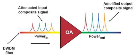
Optical amplifiers (OAs) boost the amplitude or add gain to optical signals passing on a fiber by directly stimulating the photons of the signal with extra energy. They are “in-fiber” devices. OAs amplify optical signals across a broad range of wavelengths. This is very important for DWDM system application. Erbium-doped fiber amplifiers (EDFAs) are the most commonly used type of in-fiber optical fibre. Following picture shows the operation of OA.

Optical amplifiers

  • Transponders

Transponders convert optical signals from one incoming wavelength to another outgoing wavelength suitable for DWDM applications. Transponders are optical-electricaloptical (O-E-O) wavelength converters. A transponder performs an O-E-O operation to convert wavelengths of light. Within the DWDM system a transponder converts the client optical signal back to an electrical signal (O-E) and then performs either 2R (reamplify, reshape) or 3R (reamplify, reshape, and retime) functions. The following picture shows the operation of bidirectional transponder.

Transponders

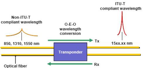
A transponder is located between a client device and a DWDM system. From left to right, the transponder receives an optical bit stream operating at one particular wavelength (1310 nm). The transponder converts the operating wavelength of the incoming bitstream to an ITU-compliant wavelength. It transmits its output into a DWDM system. On the receive side (right to left), the process is reversed. The transponder receives an ITU-compliant bit stream and converts the signals back to the wavelength used by the client device.

  • DWDM Multiplexers and Demultiplexers

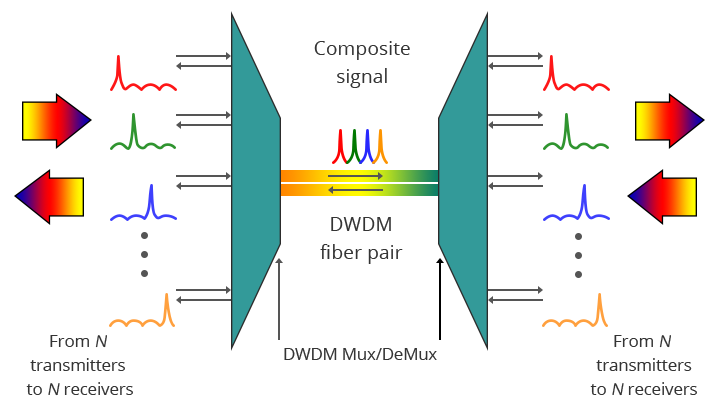
Multiple wavelengths (all within the 1550 nm band) created by multiple transmitters and operating on different fibers are combined onto one fiber by way of an optical multiplexer. The output signal of an optical multiplexer is referred to as a composite signal. At the receiving end, a demultiplexer separates all of the individual wavelengths of the composite signal out to individual fibers. The individual fibers pass the demultiplexed wavelengths to as many optical receivers. Typically, mux and demux (transmit and receive) components are contained in a single enclosure. Optical mux/demux devices can be passive. Component signals are multiplexed and demultiplexed optically, not electronically, therefore no external power source is required. Following picture shows the operation of DWDM multiplexers and demultiplexers.

DWDM Multiplex and Demultiplex

Applications for DWDM
As occurs with many new technologies, the potential ways in which DWDM can be used are only beginning to be explored. Already, however, the technology has proven to be particularly well suited for several vital applications.

  • DWDM is ready made for long-distance telecommunications operators that use either point–to–point or ring topologies. The sudden availability of 16 new transmission channels where there used to be one dramatically improves an operator’s ability to expand capacity and simultaneously set aside backup bandwidth without installing new fiber.
  • This large amount of capacity is critical to the development of self-healing rings, which characterize today’s most sophisticated telecom networks. By deploying DWDM terminals, an operator can construct a 100% protected, 40 Gb/s ring, with 16 separate communication signals using only two fibers.
  • Operators that are building or expanding their networks will also find DWDM to be an economical way to incrementally increase capacity, rapidly provision new equipment for needed expansion, and future–proof their infrastructure against unforeseen bandwidth demands.

Erbium-Doped Fiber Amplifier for DWDM Systems

Share

DWDM EDFA (Erbium-Doped Fiber Amplifier) is a key component in DWDM network systems. It uses an optical supervisory channel power adjustment and extends the power link budget for long distance DWDM communication systems. As the operating bandwidth of the EDFA has 30nm, it can zoom back of a plurality of different wavelength optical signals, and so it can be very conveniently used in DWDM systems to compensate for various optical attenuation.
With gain flattening filter, DWDM EDFA offers constant flat gain for multi-channel DWDM systems. It works at C-band or L-band, integrates electric driver, remote control, temperature control, and alarm circuits all together in a small package. It has assembled up to three pump lasers to meet the different output power levels required by DWDM systems and protect the pump failure.

FiberStore provides 40 channel BA Module DWDM EDFA. This product is spectrum flat EDFA for DWDM system. It offers high optical gain, low noise figure and high saturation optical power which are fully integrated with various kinds of DWDM systems. This DWDM EDFA has perfect network interfaces including one Ethernet RJ45 port, one RS232 port and two RS485 ports. And the open mib ensure the connectivity with all other network management system. Click here for the DWDM EDFA price.


FiberStore DWDM EDFA Features

1. Low noise figure with typical 4.5dB and high flatness with typical 1dB

2. Covers whole C-band and carries 40 or 80 channels

3. Redundancy hot swap power module with 110/220V AC and 48V DC can plug mix

5. Supports telnet and SNMP network management

6. Gain can be adjustable by network and manual

7. High precise AGC (automatic gain control) and ATC (automatic temperature control) circuits
8. High saturation output power

9. Flexible mechanics and circuit structures (Module, 1U Rack and Gain Block)

10. OEM is available and fully compatible with Telecordia GR-1312-CORE

FiberStore DWDM EDFA Functions

1. A 5V OLT 25W ATT power supply with input protection and output filtering. It is necessary to monitor the current supplied to the EDFA (this gives a measure of the aging of the device) and desirable to monitor the voltage.

2. Drive two digital input lines which control the gain of the DWDM EDFA.

3. Monitor two analog outputs which measure the input and output optical amplifier power levels.

4. Communicate with the EDFA serial port which is RS232 protocol but at TTL levels. (This allows more detailed health monitoring and setting of operating conditions that is possible using only the digital signals.)

5. Communicate with a LMA monitor and control bus. The controller is a circuit card 40mm wide by 220mm high.

Technology Of Fiber Optic Amplifiers

Share

In fiber optic communication, the visible-light or infrared (IR) beams carried by a fiber are attenuated as they travel through the material. Then there comes to the fiber optic amplifier which is used to compensate for the wakening of information during the transmission.

Amplifiers are inserted at specific places to boost optical signals in a system where the signals are weak. This boost allows the signals to be successfully transmitted through the remaining cable length. In large networks, a long series of optical fiber amplifiers are placed in a sequence along the entire network link.

Common fiber optical amplifiers include Erbium-Doped Fiber Amplifier (or EDFA Amplifier), Raman fiber amplifier, and silicon optical amplifier (SOA). Erbium doped fiber amplifier is the major type of the fiber amplifier used to boost the signal in the WDM fiber optic system, as we know it is WDM that increase the capacity of the fiber communications system and it is the erbium-doped fiber amplifier that makes WDM transmission possible. Fiber amplifiers are developed to support Dense Wavelength Division Multiplexing (DWDM) which is called DWDM EDFA amplifier and to expand to the other wavelength bands supported by fiber optics.

There are several different physical mechanisms that can be used to amplify a light signal, which correspond to the major types of optical amplifiers. In doped fibre amplifiers and bulk lasers, stimulated emission in the amplifier’s gain medium causes amplification of incoming light. In semiconductor optical amplifiers (SOAs), electron-hole recombination occurs. In Raman amplifiers, Raman scattering of incoming light with phonons in the lattice of the gain medium produces photons coherent with the incoming photons. Parametric amplifiers use parametric amplification.

When light is transmitted through matter, part of the light is scattered in random directions. A small part of the scattered light has frequencies removed from the frequency of the incident beam by quantities equal to the vibration frequencies of the material scattering system. Raman fiber optic amplifiers function within this small scattering range. If the initial beam is sufficiently intense and monochromatic, a threshold can be reached beyond which light at the Raman frequencies is amplified, builds up strongly, and generally exhibits the characteristics of stimulated emission. This is called the stimulated or coherent Raman effect.

EFDA fiber optic amplifier functions by adding erbium, rare earth ions, to the fiber core material as a dopant; typically in levels of a few hundred parts per million. The fiber is highly transparent at the erbium lasing wavelength of two to nine microns. When pumped by a laser diode, optical gain is created, and amplification occurs.

Silicon or semiconductor optical amplifier functions in a similar way to a basic laser. The structure is much the same, with two specially designed slabs of semiconductor material on top of each other, with another material in between them forming the “active layer”. An electrical current is set running through the device in order to excite electrons which can then fall back to the non-excited ground state and give out photons. Incoming optical signal stimulates emission of light at its own wavelength.

Fiber optic repeater also can re-amplify an attenuated signal but it can only function on a specific wavelength and is not suitable for WDM systems. That is the reason why optical fiber amplifier plays a much more important role in communication systems.