Tag Archives: CWDM

40GBASE-LR4 QSFP+ Transceiver Links: CWDM and PSM

Share

As we all know, 40GBASE-SR4 QSFP+ transceivers usually use a parallel multimode fiber (MMF) link to achieve 40G. It offers 4 independent transmit and receive channels, each capable of 10G operation for an aggregate data rate of 40G over 100 meters of OM3 MMF or 150 meters of OM4 MMF. However, for 40GBASE-LR4 QSFP+ transceivers, there are two kinds of links. One is coarse wavelength division multiplexing (CWDM) and the other is parallel single-mode fiber (PSM). What’s the difference between them? In this article, I will show their working principles to you respectively.

40GBASE-LR4 CWDM QSFP+ Transceiver
QSFP-40G-LR4
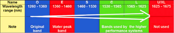
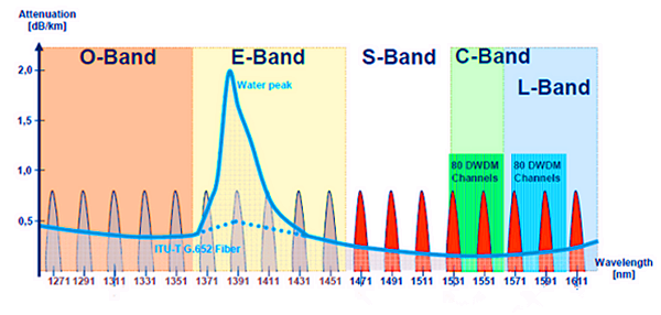
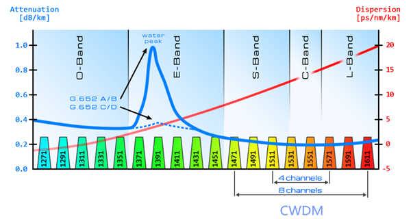
The 40GBASE-LR4 CWDM QSFP+ transceiver, such as QSFP-40GE-LR4, is compliant to 40GBASE-LR4 of the IEEE P802.3ba standard. It contains a duplex LC connector for the optical interface. The maximum transmission distance of this transceiver is 10km. To minimize the optical dispersion in the long-haul system, single-mode fiber (SMF) has to be used. This transceiver converts 4 inputs channels of 10G electrical data to 4 CWDM optical signals by a driven 4-wavelength distributed feedback (DFB) laser array, and then multiplexes them into a single channel for 40G optical transmission, propagating out of the transmitter module from the SMF. Reversely, the receiver module accepts the 40G CWDM optical signals input, and demultiplexes it into 4 individual 10G channels with different wavelengths. The central wavelengths of the 4 CWDM channels are 1271, 1291, 1311 and 1331 nm as members of the CWDM wavelength grid defined in ITU-T G694.2. Each wavelength channel is collected by a discrete photo diode and output as electric data after being amplified by a transimpedance amplifier (TIA).

40G CWDM QSFP+

40GBASE-LR4 PSM QSFP+ Transceiver
40G-LR4 QSFPUnlike CWDM QSFP+ transceiver which uses a LC connector, PSM QSFP+ is a parallel single-mode optical transceiver with an MTP/MPO fiber ribbon connector. It also offers 4 independent transmit and receive channels, each capable of 10G operation for an aggregate data rate of 40G on 10km of single-mode fiber. Proper alignment is ensured by the guide pins inside the receptacle. The cable usually cannot be twisted for proper channel to channel alignment. In terms of a PSM QSFP+, the transmitter module accepts electrical input signals compatible with common mode logic (CML) levels. All input data signals are differential and internally terminated. The receiver module converts parallel optical input signals via a photo detector array into parallel electrical output signals. The receiver module outputs electrical signals are also voltage compatible with CML levels. All data signals are differential and support a data rates up to 10.3G per channel.

40G PSM QSFP+

What’s the Difference?
From an optical transceiver module structure viewpoint, PSM seems more cost effective because it uses a single uncooled CW laser which splits its output power into four integrated silicon modulators. Besides, its array-fiber coupling to an MTP connector is relatively simple. However, from an infrastructure viewpoint, PSM would be more expensive when the link distance is long, mainly due to the fact that PSM uses 8 optical single-mode fibers while CWDM uses only 2 optical single-mode fibers. A summary table comparing the key differences between CWDM and PSM is shown below:

Name CWDM PSM
Optical TX 4 uncooled 1300nm CWDM directly-modulated laserswavelength spacing 20 nm 4 integrated silicon photonic modulators and one CW laseruncooled 1300nm DFB laser
4-wavelength CWDM multiplexer and demultiplexer Needed No need
Connector Duplex LC connector MTP/MPO fiber ribbon connector
Cable Via 2 optical single-mode fibers Via 8 optical single-mode fibers

In addition, the caveat is that the entire optical fiber infrastructure within a data center, including patch panels, has to be changed to accommodate MTP connectors and ribbon cables, which are more expensive than conventional LC connectors and regular SMF cables. What’s more, cleaning MTP connectors is not a straightforward task. Therefore, CWDM is a more profitable and popular 40G QSFP link.

Conclusion
For 40GBASE-LR4 QSFP+ transceivers, either CWDM link or PSM link, the maximum transmission distance is both 10km. 40GBASE-LR4 CWDM QSFP+ transceivers use a duplex LC connector via 2 optical single-mode fibers to achieve 40G. However, 40GBASE-LR4 PSM QSFP+ transceivers use an MTP/MPO fiber ribbon connector via 8 optical single-mode fibers to reach 40G. Therefore, CWDM QSFP+ enables data center operators to upgrade to 40G connectivity without making any changes to the previous 10G fiber cable plant, which is more cost-effective and widely used by people. Fiberstore provides wide brand compatible 40G CWDM QSFP+ transceivers, such as Juniper compatible JNP-QSFP-40G-LR4 and HP compatible JG661A. In Fiberstore, each fiber optic transceiver has been tested to ensure its compatibility and interoperability. Please rest assured to buy. For more information or quotation, please contact us via sales@fs.com.

Related Article: 40G Transceiver Module: QSFP+ Module And CFP Module

From O to L: the Evolution of Optical Wavelength Bands

Share

In optical fiber communications system, several transmission bands have been defined and standardized, from the original O-band to the U/XL-band. The E- and U/XL-bands have typically been avoided because they have high transmission loss regions. The E-band represents the water peak region, while the U/XL-band resides at the very end of the transmission window for silica glass.

Optical Wavelength Bands

Intercity and metro ring fiber already carry signals on multiple wavelengths to increase bandwidth. Fibers entering the home will soon do the same. Now there are several types of optical telecom systems have been developed, some based on time division multiplexing (TDM) and others on wavelength division multiplexing (WDM), either dense wavelength division multiplexing (DWDM) or coarse wavelength division multiplexing (CWDM). This article may represent the evolution of optical wavelength bands mainly by describing these three high-performance systems.

Dense Wavelength Division Multiplexing
DWDM systems were developed to deal with the rising bandwidth needs of backbone optical networks. The narrow spacing (usually 0.2 nm) between wavelength bands increases the number of wavelengths and enables data rates of several Terabits per second (Tbps) in a single fiber.

These systems were first developed for laser-light wavelengths in the C-band, and later in the L-band, leveraging the wavelengths with the lowest attenuation rates in glass fiber as well as the possibility of optical amplification. Erbium-doped fiber amplifiers (EDFAs, which work at these wavelengths) are a key enabling technology for these systems. Because WDM systems use many wavelengths at the same time, which may lead to much attenuation. Therefore optical amplification technology is introduced. Raman amplification and erbium-doped fiber amplifiers are two common types used in WDM system.

DWDM

In order to meet the demand for “unlimited bandwidth,” it was believed that DWDM would have to be extended to more bands. In the future, however, the L-band will also prove to be useful. Because EDFAs are less efficient in the L-band, the use of Raman amplification technology will be re-addressed, with related pumping wavelengths close to 1485 nm.

Coarse Wave Division Multiplexing
CWDM is the low-cost version of WDM. Generally these systems are not amplified and therefore have limited range. They typically use less expensive light sources that are not temperaturestabilized. Larger gaps between wavelengths are necessary, usually 20 nm. Of course, this reduces the number of wavelengths that can be used and thus also reduces the total available bandwidth.

CWDM

Current systems use the S-, C- and L-bands because these bands inhabit the natural region for low optical losses in glass fiber. Although extension into the O and E-band (1310 nm to 1450 nm) is possible, system reach (the distance the light can travel in fiber and still provide good signal without amplification) will suffer as a result of losses incurred by use of the 1310 nm region in modern fibers.

Time Division Multiplexing
TDM systems use either one wavelength band or two (with one wavelength band allocated to each direction). TDM solutions are currently in the spotlight with the deployment of fiber-to-the-home (FTTH) technologies. Both EPON and GPON are TDM systems. The standard bandwidth allocation for GPON requires between 1260 and 1360 nm upstream, 1440 to 1500 nm downstream, and 1550 to 1560 nm for cable-TV video.

To meet the rise in bandwidth demand, these systems will require upgrading. Some predict that TDM and CWDM (or even DWDM) will have to coexist in the same installed network fibers. To achieve this, work is underway within the standardization bodies to define filters that block non-GPON wavelengths to currently installed customers. This will require the CWDM portion to use wavelength bands far away from those reserved for GPON. Consequently, they will have to use the L-band or the C- and L-bands and provided video is not used.

tdm

Conclusion
In each case, sufficient performance has been demonstrated to ensure high performance for today’s and tomorrow’s systems. From this article, we know that the original O-band hasn’t satisfied the rapid development of high bandwidth anymore. And the evolution of optical wavelength bands just means more and more bands will be called for. In the future, with the growth of FTTH applications, there is no doubt that C- and L-bands will play more and more important roles in optical transmission system. Fiberstore offer all kinds of products for WDM optical network, such as CWDM/DWDM MUX DEMUX and EDFA. For more information, please visit www.fs.com.

Wavelength Selective Couplers and Splitters

Share

Wavelength Selective Couplers (or Splitters) are used to either combine or split light of different wavelengths with minimal loss. Light of two different wavelengths on different input fibers can be merged (combined) onto the same output fiber. In the reverse direction light of two different wavelengths on the same fiber can be split so that one wavelength goes to one output fiber and the other wavelength is output onto the other output fiber. The process can be performed with very little loss.

As the coupling length is wavelength dependent, the shifting of power between the two parallel waveguides will take place at different places along the coupler for different wavelengths. All we need to do is choose the coupling length carefully and we can arrange for loss free wavelength combining or splitting. These functions are shown in the figure below. The graph of power transfer shows how power input on one of the fibers shifts back and forth between the two waveguides. The period of the shift is different for the two different wavelengths. Thus in the left-hand section of the diagram (combining wavelengths) there will be a place down the coupler where all of the light is in only one waveguide. If we make the coupler exactly this length then the signals have been combined. On the right-hand side of the diagram the reverse process is shown where two different wavelengths arrive on the same input fiber. At a particular point down the coupler the wavelengths will be in different waveguides so if we make this the coupling length then we have separated the wavelengths exactly. In fact both the processes described above are performed in the same coupler—the process is Bi-Directional (BiDi). Thus the coupler on the left can operate in the opposite direction and become a splitter and the splitter on the right can operate in the opposite direction and become a coupler (combiner). Note that each coupler or splitter must be designed for the particular wavelengths to be used.

Wavelength Selective Coupling and Splitting

Commercial devices of this kind are commonly available and are very efficient. The quoted insertion loss is usually between 1.2 and 1.5 dB and the channel separation is quoted as better than 40 dB. “Wavelength flattened” couplers or splitters of this kind operate over quite a wide band of wavelengths. That is a given device may allow input over a range of wavelengths in the 1310 nm band up to 50 nm wide and a range of wavelengths in the 1550 nm band also up to 50 nm wide.

Power Input to an EDFA

On the left-hand side of the figure we see an example of coupling two different wavelengths into the same output fiber. At the input of an EDFA you want to mix the (low level) incoming signal light with (high level) light from the pump. Typically the signal light will be around 1550 nm and the pump will be 980 nm. In this case it is possible to choose a coupling length such that 100% of the signal light and 100% of the pump light leaves on the same fiber. A major advantage of this is that there is very little loss of signal power in this process.

Splitting Wavelengths for CWDM Systems

On the right-hand side of the figure we show an example of CWDM demultiplexing. A mixed wavelength stream with one signal in each of the 1300 and 1550 nm bands is separated into its two component wavelengths. A CWDM system like this might be used in a system for distributing CATV and advanced VOD services to people in their homes. One signal stream might be carried at 1310 nm and the other at 1550 nm. A resonant coupler is shown here operating as a splitter separating the two wavelengths. Note that an identical splitter could also be used to combine the two wavelengths with very little loss.

Adding the Management Channel in DWDM Systems

In DWDM systems where many channels are carried in the 1550 nm band there is often a requirement to carry an additional relatively slow rate channel for management purposes. A convenient way to do this is to send the management information in the 1310 nm band and the mixed DWDM stream in the 1550 band. Wavelength selective couplers are commonly used for this purpose. A management signal (a single wavelength) in the 1310 band is coupled onto a fiber carrying many wavelengths between 1540 nm and 1560 nm. Another similar device (wavelength selective splitter) is used to separate the signals at the other end of the link.

Article Source: http://www.fiberopticshare.com/wavelength-selective-couplers-and-splitters.html

The More and More Mature Fiber Optic Cables Transmission Technology

Share

Fiber optic media are any network transmission media that generally use glass, or plastic fiber in some special cases, to transmit network data in the form of light pulses. Within the last decade, optical fiber has become an increasingly popular type of network transmission media as the need for higher bandwidth and longer spans continues.

Fiber optic technology is different in its operation than standard copper media because the transmissions are “digital” light pulses instead of electrical voltage transitions. Very simply, fiber optic transmissions encode the ones and zeroes of a digital network transmission by turning on and off the light pulses of a laser light source, of a given wavelength, at very high frequencies. The light source is usually either a laser or some kind of Light-Emitting Diode (LED). The light from the light source is flashed on and off in the pattern of the data being encoded. The light travels inside the fiber until the light signal gets to its intended destination and is read by an optical detector.

Fiber optic cables are optimized for one or more wavelengths of light. The wavelength of a particular light source is the length, measured in nanometers (billionths of a meter, abbreviated “nm”), between wave peaks in a typical light wave from that light source. You can think of a wavelength as the color of the light, and it is equal to the speed of light divided by the frequency. In the case of Single-Mode Fiber (SMF), many different wavelengths of light can be transmitted over the same optical fiber at any one time. This is useful for increasing the transmission capacity of the fiber optic cable since each wavelength of light is a distinct signal. Therefore, many signals can be carried over the same strand of optical fiber. This requires multiple lasers and detectors and is referred to as Wavelength-Division Multiplexing (WDM).

Typically, optical fibers use wavelengths between 850 and 1550 nm, depending on the light source. Specifically, Multi-Mode Fiber (MMF) is used at 850 or 1300 nm and the SMF is typicallyused at 1310, 1490, and 1550 nm (and, in WDM systems, in wavelengths around these primary wavelengths). The latest technology is extending this to 1625 nm for SMF that is being used for next-generation Passive Optical Networks (PON) for FTTH (Fiber-To-The-Home) applications. Silica-based glass is most transparent at these wavelengths, and therefore the transmission is more efficient (there is less attenuation of the signal) in this range. For a reference, visible light (the light that you can see) has wavelengths in the range between 400 and 700 nm. Most fiber optic light sources operate within the near infrared range (between 750 and 2500 nm). You can’t see infrared light, but it is a very effective fiber optic light source.

Above: Multimode fiber is usually 50/125 and 62.5/125 in construction. This means that the core to cladding diameter ratio is 50 microns to 125 microns and 62.5 microns to 125 microns.  There are several types of multimode fiber patch cable available today,  the most common are multimode sc patch cable fiber, LC, ST, FC, ect.

Tips: Most traditional fiber optic light sources can only operate within the visible wavelength spectrum and over a range of wavelengths, not at one specific wavelength. Lasers (light amplification by stimulated emission of radiation) and LEDs produce light in a more limited, even single-wavelength, spectrum.

WARNING: Laser light sources used with fiber optic cables (such as the OM3 cables) are extremely hazardous to your vision. Looking directly at the end of a live optical fiber can cause severe damage to your retinas. You could be made permanently blind. Never look at the end of a fiber optic cable without first knowing that no light source is active.

The attenuation of optical fibers (both SMF and MMF) is lower at longer wavelengths. As a result, longer distance communications tends to occur at 1310 and 1550 nm wavelengths over SMF. Typical optical fibers have a larger attenuation at 1385 nm. This water peak is a result of very small amounts (in the part-per-million range) of water incorporated during the manufacturing process. Specifically it is a terminal –OH(hydroxyl) molecule that happens to have its characteristic vibration at the 1385 nm wavelength; thereby contributing to a high attenuation at this wavelength. Historically, communications systems operated on either side of this peak.

When the light pulses reach the destination, a sensor picks up the presence or absence of the light signal and transforms the pulses of light back into electrical signals. The more the light signal scatters or confronts boundaries, the greater the likelihood of signal loss (attenuation). Additionally, every fiber optic connector between signal source and destination presents the possibility for signal loss. Thus, the connectors must be installed correctly at each connection. There are several types of fiber optic connectors available today. The most common are: ST, SC, FC, MT-RJ and LC style connectors. All of these types of connectors can be used with either multimode or single mode fiber.

Most LAN/WAN fiber transmission systems use one fiber for transmitting and one for reception. However, the latest technology allows a fiber optic transmitter to transmit in two directions over the same fiber strand (e.g, a passive cwdm mux using WDM technology). The different wavelengths of light do not interfere with each other since the detectors are tuned to only read specific wavelengths. Therefore, the more wavelengths you send over a single strand of optical fiber, the more detectors you need.

Related Article:  Which Patch Cable Should I Choose for My Optical Transceiver?