Tag Archives: CFP Transceiver

Knowledge of Multi-source Agreement

Share

Fiber Optical TransceiverWe usually see some products that are compliant with MSA when refers to fiber optic transceivers, but what does MSA mean? It seems like a standard that is used to define the optical transceiver. In fact, MSAs are not official standards organizations. Instead, they are agreements that equipment vendors assume when developing form factors for communications interfaces. These form factors, usually called the transceiver modules, are typically deployed in active electronics such as switches, servers and multiplexers. In this text, some knowledge of the MSA will be introduced.

What is Multi-source Agreement?

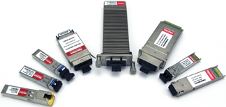
MSA stands for multi-source agreement, which is an agreement between multiple manufacturers to make products which are compatible across vendors, acting as de facto standards, establishing a competitive market for interoperable products. Products that adhere to MSAs include optical transceivers (SFP, SFP+, XENPAK, QSFP, XFP, etc), fiber optic cables, and other networking devices. MSAs strictly define the operating characteristics of these optical transceivers so that system vendors may implement ports in their devices that allow MSA compliant transceivers produced by name brand, as well a third party vendors, to function properly. That is, transceivers may be purchased from any of the multiple sources in the open market, like Fiberstore. MSAs are also important in the cabling industry as the density, line speed, power consumption and typical costs of a MSA can strongly impact its success in the marketplace. This, in turn, can drive the choice for both connector and media type.

Why is Multi-source Agreement  so Important?

Equipment vendors all rely on MSAs when designing their systems, ensuring interoperability and interchangeability between interface modules, that is every supplier can produce the transceiver modules with the same functions. For this reason, there are many module suppliers from which customers can choose freely. As we all know, freedom of choice is the foundation of the efficient operation of markets. In order to gain a bigger share of the market, suppliers may act as efficiently as possible, which may drive down costs and offer the widest options to customers. Besides, since there are so many excellent 3rd party optical transceiver module suppliers in the market that network operators don’t need to purchase optical transceivers directly from system (original brand) vendors, which will also save huge costs. Finally, there is no doubt that all these will help support and encourage creation and adherence to standards at the same time. Over the past decade, the MSA process has helped accelerate the acceptance of modules such as SFP+ and CFP, which allow optical transceivers to support greater bandwidth such as 40G and 100G.

Approved Fiber Optica Transceiver Multi-source Agreements

MSA is a popular industry format jointly developed and supported by many network component vendors, most common optical transceivers are specified by it at present. MSAs usually specify parameters for optical transceivers and their guideline values, such as the electrical and optical interfaces (e.g. SX, LX, EX, ZX, etc), mechanical dimensions, electro-magnetic values and other data. This data is accessible by the host system over the I2C interface, as is the status of the optional DDM functions. Some approved fiber optica transceiver multi-source agreements are listed in the table below:

Name Year Brief Description Keywords/Applications
GBIC 2000 GigaBit Interface Converter Designed for Gigabit Ethernet, SDH/SONET (2.5 Gb/s) and Fibre Channel (4Gb/s). Superseded by SFP
SFP 2001 Small Form-factor Pluggable Designed for Gigabit Ethernet, SDH/SONET (2.5 Gb/s) and Fibre Channel (4Gb/s)
XENPAK 2001 Fiber optic transceiver for 10Gb Ethernet Superseded by X2 and SFP+
X2 2005 Fiber optic transceiver for 10Gb Ethernet Superseded by SFP+
XFP 2005 Fiber optic transceiver for 10Gb Ethernet Designed for 10Gb/s. Supports 8Gb/s Fibre Channel, 10 Gb/s Ethernet and Optical Transport Network
SFP+ 2013 Fiber optic transceiver for 10Gb Ethernet Designed for 10Gb/s. Supports 8Gb/s Fibre Channel, 10 Gb/s Ethernet and Optical Transport Network standard OTU2
QSFP/QSFP+ 2013 Quad Small Form-factor Pluggable 40G Supports Ethernet, Fibre Channel, InfiniBand and SONET/SDH standards up to 40GB/s and 100Gb/s
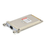
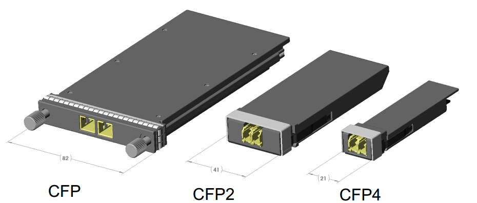
CFP 2013 C Form Factor Pluggable (100G) Optical transceiver form factors supporting 40Gb/s and 100Gb/s. CFP, CFP2 and CFP4
CXP In Progress C Form Factor Pluggable Supports Infiniband and Ethernet to 100G. CXP and CXP2

What’s Difference Between CFP and CXP Transceivers?

Share

Two years ago, though everyone is talking about the 100G Ethernet as the next generation, it had still faced a lot of problems to be solved, seeming to be a long way off. But, technologies are developed very rapidly, and now 100G Ethernet is becoming more and more closer to us. Fiber connectivity in higher-speed active equipment is being condensed and simplified with plug-and-play, hot-swap transceiver miniaturization. Thus, optical transceiver technology is one of the basic but important technology to achieve the realiable and effective 100G Ethernet. Interfaces for 100G active equipment include CFP and CXP. So, what are CFP and CXP? And what’s the difference between CFP and CXP? Is CXP transceiver designed to replace the CFP? … You might be interested in them and have a lot of questions in your mind. Today, you will find the answer in this post.

About CFP
cfp-100g85-1m-ju-01CFP, short for C form-factor pluggable, is a multi-source agreement to produce a common form-factor for the transmission of high-speed digital signals. The c stands for the Latin letter C used to express the number 100 (centum), since the standard was primarily developed for 100 Gigabit Ethernet systems. In fact, CFP also supports the 40GbE. When talking about CFP, we always define it as multipurpose CFP, compared to the CXP which is discussed later.

The CFP MSA was formally launched at OFC/NFOEC 2009 in March by founding members Finisar, Opnext, and Sumitomo/ExceLight. The CFP form factor, as detailed in the MSA, supports both single-mode and multi-mode fiber and a variety of data rates, protocols, and link lengths, including all the physical media-dependent (PMD) interfaces encompassed in the IEEE 802.3ba standard. At 40GE, target optical interfaces include the 40GBase-SR4 for 100 meters (m) and the 40GBase-LR4 for 10 kilometers (km). There are three PMDs for 100 GE: 100GBase-SR10 for 100 m, 100GBase-LR4 for 10 km, and 100GBase-ER4 for 40 km.

CFP was designed after the Small Form-factor Pluggable transceiver (SFP) interface, but is significantly larger to support 100Gbps. The electrical connection of a CFP uses 10 x 10Gbps lanes in each direction (RX, TX). The optical connection can support both 10 x 10Gbps and 4 x 25Gbps variants. CFP transceivers can support a single 100Gbps signal like 100GE or OTU4 or one or more 40Gbps signals like 40GE, OTU3, or STM-256/OC-768.

The CFP-MSA Committee has defined three form factors:

  • CFP – Currently at standard revision 1.4 and is widely available in the market
  • CFP2 – Currently at draft revision 0.3 is half the size of the CFP transceiver; these are recently available in the market
  • CFP4 – Standard is not yet available, is half the size of a CFP2 transceiver, not yet available

CFP transceiver today to future

The original CFP specification was proposed at a time when 10Gbps signals were far more achievable than 25Gbps signals. As such to achieve 100Gbps line rate, the most affordable solution was based on 10 lanes of 10Gbps. However as expected, improvements in technology has allowed higher performance and higher density. Hence the development of the CFP2 and CFP4 specifications. While electrical similar, they specify a form-factor of 1/2 and 1/4 respectively in size of the original specification. Note that CFP, CFP2 and CFP4 modules are not interchangable (but would be interoperable at the optical interface with approriate connectors).

About CXP
CXP
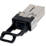
CXP is targeted at the clustering and high-speed computing markets, so we usually called it high-density CXP. Technically, the CFP will work with multimode fiber for short-reach applications, but it is not really optimized in size for the multimode fiber market, most notably because the multimode fiber market requires high faceplate density. The CXP was created to satisfy the high-density requirements of the data center, targeting parallel interconnections for 12x QDR InfiniBand (120 Gbps), 100 GbE, and proprietary links between systems collocated in the same facility. The InfiniBand Trade Association is currently standardizing the CXP.

The CXP is 45 mm in length and 27 mm in width, making it slightly larger than an XFP. It includes 12 transmit and 12 receive channels in its compact package. This is achieved via a connector configuration similar to that of the CFP. For perspective, the CXP enables a front panel density that is greater than that of an SFP+ running at 10 Gbps.

Typical applications of CXP in the data center include 100GE over Copper (CXP): 7m (23ft) and 100GE over multimode fiber: CXP for short reach applications (CFP is used for longer reach applications).

What’s the Difference Between CFP and CXP?
Despite having a similar acronym and emerging at roughly the same time, the CFP and CXP form factors are markedly different in terms of size, density, and intended application. The CFP and CXP optical transceiver form factors are hot pluggable, both feature transmit and receive functions, and both support data rates of 40 and 100 Gbps. But the similarities begin and end there. Aimed primarily at 40- and 100-Gigabit Ethernet (GbE) applications, the CFP supports both singlemode and multimode fiber and can accommodate a host of data rates, protocols, and link lengths. The CXP, by contrast, is targeted at the clustering and high-speed computing markets. The two are therefore complementary, not competitive, according to several sources. Thus, the existence of CXP does not mean the replacing of CFP.

However, things are never black and white. In some case, there is a competition between CFP and CXP, as CFP can also be used with multimode fiber. It becomes more of a choice for system vendors. Do they need to build a box that can adapt to any interface? If so, they would probably use CFP. If it’s a box that is just focused on the short-reach market, then they would probably use something more like CXP.

I hope this post will let you more understanding the 100GbE transceivers, whether CFP or CXP. Similarly, you could kown the 40GbE transceiver through this post as the CFP and CXP also support the 40GbE. If you want to have a further study on this subject, I suggest you to learn the related refference of MSA.

Article Source: http://www.fiber-optic-transceiver-module.com/whats-difference-between-cfp-and-cxp-transceivers.html

A Complete Guide of Installing or Removing Transceiver Modules (Part III)

Share

Monday again, welcome to my blog. This week, we are going to finish the topic “A Complete Guide of Installing or Removing Transceiver Modules”. As we know, we continue this topic for almost three weeks, and today, we will explain the Part III, ie. the last part. The Part III is explaining mainly the installation and remove of QSFP/QSFP+ and CFP.

After learning the Part I and Part II, you may have a better understanding of installing or removing transceiver modules, such as SFP, X2, GBIC, XENPAK or XFP etc. You may also find that the different transceivers are similar in the installing or removing steps. Nonetheless, there is unique feature of different transceiver modules which affect the installing and removing, so that we should be carefully and understand each type of transceiver. OK, now we are return to today’s main topic – How to Install or Remove the QSFP/QSFP+ and CFP.

How to Install or Remove QSFP/QSFP+ Transceiver Module

QSFP/QSFP+ Installing Steps
step 1: Attach an ESD wrist strap to yourself and a properly grounded point on the chassis or the rack.
step 2: Remove the QSFP+ transceiver module from its protective packaging.
step 3: Check the label on the QSFP+ transceiver module body to verify that you have the correct model for your network.
step 4: For optical QSFP+ transceivers, remove the optical bore dust plug and set it aside.
step 5: For transceivers equipped with a bail-clasp latch:
a. Keep the bail-clasp aligned in a vertical position.
b. Align the QSFP+ transceiver in front of the module’s transceiver socket opening and carefully slide the QSFP+ transceiver into the socket until the transceiver makes contact with the socket electrical connector.

step 6: For QSFP+ transceivers equipped with a pull-tab:
a. Hold the transceiver so that the identifier label is on the top.
b. Align the QSFP+ transceiver in front of the module’s transceiver socket opening and carefully slide the QSFP+ transceiver into the socket until the transceiver makes contact with the socket electrical connector.

step 7: Press firmly on the front of the QSFP+ transceiver with your thumb to fully seat the transceiver in the module’s transceiver socket.
Please Note: If the latch is not fully engaged, you might accidentally disconnect the QSFP+ transceiver module.

step 8: For optical QSFP+ modules, reinstall the dust plug into the QSFP+ transceivers optical bore until you are ready to attach the network interface cable. Please Note: Do not remove the dust plug until you are ready to attach the network interface cable.

QSFP/QSFP+ Removing Steps
step 1: For optical QSFP+ transceivers, disconnect the network interface cable from the QSFP+ transceiver connector.
step 2: For QSFP+ transceivers equipped with a bail-clasp latch.
a. Pivot the bail-clasp down to the horizontal position.
b. Immediately install the dust plug into the transceivers optical bore.
c. Grasp the sides of the QSFP+ transceiver and slide it out of the module socket.

step 3: For QSFP+ transceivers equipped with a pull tab latch
a. Immediately install the dust plug into the transceiver’s optical bore.
b. Grasp the tab and gently pull to release the transceiver from the socket.
c. Slide the transceiver out of the socket.

step 4: Place the QSFP+ transceiver into an antistatic bag.

How to Install or Remove CFP Transceiver Module

CFP Installing Steps
step 1: Remove the CFP transceiver from its protective packaging.
step 2: Check the label on the CFP transceiver body to verify that you have the correct model for your network.
step 3: Remove the dust plug from the CFP transceiver module optical port and set it aside.
step 4: Align the CFP device into the transceiver port socket of your networking module, and slide it in until the CFP transceiver EMI gasket flange makes contact with the module faceplate.
step 5: Press firmly on the front of the CFP transceiver with your thumb to fully seat it in the transceiver socket.
step 6: Gently tighten the two captive installation screws on the transceiver to secure the CFP transceiver in the socket.
step 7: Reinstall the dust plug into the CFP transceiver’s optical bore until you are ready to attach the network interface cable.
step 8: When you are ready to attach the network cable interface, remove the dust plugs and inspect and clean fiber connector end faces, and then immediately attach the network interface cable connectors into the CFP transceiver optical bores.

CFP Removing Steps
step 1: Disconnect the network fiber-optic cable from the CFP transceiver connectors. Immediately reinstall the dust plugs in the CFP transceiver optical bores.
step 2: Loosen the two captive installation screws that secure the CFP to the networking module.
step 3: Slide the CFP transceiver out of the module socket. Immediately place the CFP transceiver in antistatic protective packaging.

Author’s Note
Up to here, the topic “A Complete Guide of Installing or Removing Transceiver Modules” has already finished. Thanks all the reader for continued focusing. In fact, the installing or removing steps of the mentioned transceiver modules are the general case. Different transceiver modules of different brands have their own features. We should ask the vendor to get more informations when you face a problem that we do not mentioned here. In addition, to save more money, we suggest that compatible 3rd transceiver modules may be another good choice but you should ensure that your vendor is reliable. Fiberstore‘s fiber optic transceivers are 100% compatible with major brands like Cisco, HP, Juniper, Nortel, Force10, D-link, 3Com. They are backed by a lifetime warranty so that you can buy with confidence. Additionally, customize optical transceivers to fit your specific requirements are available. If you have any requirement of transceivers, Fiberstore will be a good choice for you.

Article Source: http://www.fiber-optic-transceiver-module.com/a-complete-guide-of-installing-or-removing-transceiver-modules-part-iii.html