Category Archives: WDM System

Some Developments that May Occur in the Fiber Amplifier

Share

This page will focus on fiber optic amplifiers?application, and obviously, the introduction of EDFA in a long distance network has been the first, application identified by several telecom’s operators. I just think EDFA’s advantage is that using the existing cable from 565 Mbit/s systems. Into a 2400 Mbit/s without any additional electronic requirement, maybe this is one of the cost/performance ratio advantage of the optical amplifier versus the conventional technologies. Other applications arise from those countries where the telecommunication network infrastructures are poor, or even non existing. In such a situation the possibility to reach a distance in the order of 200km at 140 or 565 Mbit/s makes the use of EDFA more competitive.

Optical amplification has been already successfully tested in various laboratories and field trials in Europe, North America and Japan. Worldwide standards authority is still working on the standardization of EDFA optical amplifier. Major telecom manufactures already supply line terminals with integrated optical amplifier functions. As far as the future submarine links are concerned, it is expected that in a few years, because of optical amplification, the electronical of today submerged repeaters, will be amended by replacing all optical amplifiers.

Well, an example of the power budget calculations at 2400 Mbit/s is given in the annex, where an EDFA system composed by a power amplifier and a pre-amplifier has been considered. In combination with a dispersion shifted submarine fiber optic cable, it belongs to outdoor fiber optic cable. Junction Networks. The massive introduction of SDH systems, and the forecast use of it on the existing cables, has made the use of EDFA technologies achievable also in the junction networks area. In Europe, North America and Japan, this possibility will be limited to the intercity applications.

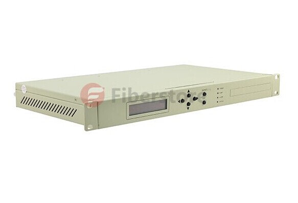
In connection with the subscriber loop network design, a similar range of products is drawn up by the worldwide industry for the next generation of CATV systems. It is CATV amplifier. In a near future optical transmitters with Booster Amplifier? integrated in the same equipment, will need to be able to transmit up to 60/80 television channels simultaneously, in a cluster of 200/300 subscribers each. The figure showed a?Booster EDFA Optical Amplifier.

edfa

Although CATV amplifier housing employed in current CATV networks is designed to accommodate a return path amplifier, most of today’s CATV system have unactivated return channels. Roughly 20 percent of today’s CATV systems use some fiber optic links to bypass slow amplifier chains in the trunk portion of the network. Service is typically provided to residences and apartments, with relatively limited business locations connected to CATV networks. Similar applications product has WDM amplifier. In-line amplifier, just differ in the range of applications. There is usually only a single CATV operator in a given service area, with nascent competition from microwave and direct broadcast satellite service providers. Television receives only background antennas that are 1 to 2 meters in diameter are used by a small fraction of residential customers. With the fast developments of fiber optical amplifiers, I am very bullish on the trend of it, hope it can be dragged out more widely features and bring more benefits to people.

Related Article:  Which Patch Cable Should I Choose for My Optical Transceiver?

The More and More Mature Fiber Optic Cables Transmission Technology

Share

Fiber optic media are any network transmission media that generally use glass, or plastic fiber in some special cases, to transmit network data in the form of light pulses. Within the last decade, optical fiber has become an increasingly popular type of network transmission media as the need for higher bandwidth and longer spans continues.

Fiber optic technology is different in its operation than standard copper media because the transmissions are “digital” light pulses instead of electrical voltage transitions. Very simply, fiber optic transmissions encode the ones and zeroes of a digital network transmission by turning on and off the light pulses of a laser light source, of a given wavelength, at very high frequencies. The light source is usually either a laser or some kind of Light-Emitting Diode (LED). The light from the light source is flashed on and off in the pattern of the data being encoded. The light travels inside the fiber until the light signal gets to its intended destination and is read by an optical detector.

Fiber optic cables are optimized for one or more wavelengths of light. The wavelength of a particular light source is the length, measured in nanometers (billionths of a meter, abbreviated “nm”), between wave peaks in a typical light wave from that light source. You can think of a wavelength as the color of the light, and it is equal to the speed of light divided by the frequency. In the case of Single-Mode Fiber (SMF), many different wavelengths of light can be transmitted over the same optical fiber at any one time. This is useful for increasing the transmission capacity of the fiber optic cable since each wavelength of light is a distinct signal. Therefore, many signals can be carried over the same strand of optical fiber. This requires multiple lasers and detectors and is referred to as Wavelength-Division Multiplexing (WDM).

Typically, optical fibers use wavelengths between 850 and 1550 nm, depending on the light source. Specifically, Multi-Mode Fiber (MMF) is used at 850 or 1300 nm and the SMF is typicallyused at 1310, 1490, and 1550 nm (and, in WDM systems, in wavelengths around these primary wavelengths). The latest technology is extending this to 1625 nm for SMF that is being used for next-generation Passive Optical Networks (PON) for FTTH (Fiber-To-The-Home) applications. Silica-based glass is most transparent at these wavelengths, and therefore the transmission is more efficient (there is less attenuation of the signal) in this range. For a reference, visible light (the light that you can see) has wavelengths in the range between 400 and 700 nm. Most fiber optic light sources operate within the near infrared range (between 750 and 2500 nm). You can’t see infrared light, but it is a very effective fiber optic light source.

Above: Multimode fiber is usually 50/125 and 62.5/125 in construction. This means that the core to cladding diameter ratio is 50 microns to 125 microns and 62.5 microns to 125 microns.  There are several types of multimode fiber patch cable available today,  the most common are multimode sc patch cable fiber, LC, ST, FC, ect.

Tips: Most traditional fiber optic light sources can only operate within the visible wavelength spectrum and over a range of wavelengths, not at one specific wavelength. Lasers (light amplification by stimulated emission of radiation) and LEDs produce light in a more limited, even single-wavelength, spectrum.

WARNING: Laser light sources used with fiber optic cables (such as the OM3 cables) are extremely hazardous to your vision. Looking directly at the end of a live optical fiber can cause severe damage to your retinas. You could be made permanently blind. Never look at the end of a fiber optic cable without first knowing that no light source is active.

The attenuation of optical fibers (both SMF and MMF) is lower at longer wavelengths. As a result, longer distance communications tends to occur at 1310 and 1550 nm wavelengths over SMF. Typical optical fibers have a larger attenuation at 1385 nm. This water peak is a result of very small amounts (in the part-per-million range) of water incorporated during the manufacturing process. Specifically it is a terminal –OH(hydroxyl) molecule that happens to have its characteristic vibration at the 1385 nm wavelength; thereby contributing to a high attenuation at this wavelength. Historically, communications systems operated on either side of this peak.

When the light pulses reach the destination, a sensor picks up the presence or absence of the light signal and transforms the pulses of light back into electrical signals. The more the light signal scatters or confronts boundaries, the greater the likelihood of signal loss (attenuation). Additionally, every fiber optic connector between signal source and destination presents the possibility for signal loss. Thus, the connectors must be installed correctly at each connection. There are several types of fiber optic connectors available today. The most common are: ST, SC, FC, MT-RJ and LC style connectors. All of these types of connectors can be used with either multimode or single mode fiber.

Most LAN/WAN fiber transmission systems use one fiber for transmitting and one for reception. However, the latest technology allows a fiber optic transmitter to transmit in two directions over the same fiber strand (e.g, a passive cwdm mux using WDM technology). The different wavelengths of light do not interfere with each other since the detectors are tuned to only read specific wavelengths. Therefore, the more wavelengths you send over a single strand of optical fiber, the more detectors you need.

Related Article:  Which Patch Cable Should I Choose for My Optical Transceiver?

Some Knoweledge About Erbium-droped Fiber Amplifer

Share

The eribum-doped fiber amplifier (EDFA) was first reported in 1987, and, in the short period since then, its applications have transformed the optical communications industry. Before the advent of optical amplifers, optical transmission systems typically consisted of a digital transmitter and a receivere separated by spans of transmission optical fiber intersersed with optoelectronic regenerators. The optoelectronic regenerators corrected attenuation, dispersion, and other transmission degradations of the optical signal by detecting the attenuated and distorted data pulses, electronically reconstituting them, and then optically transmitting the regenerated data into the next transmission span.

The EDFA is an optical amplifer that faithfully amplifies lightwave signals purely in the optical domain. EDFAs have several potential functions in optical fiber transmission systems. They can be used as power amplifiers to boost transmitter power, as repeaters or in-line amplifiers to increase system reach, or as preamplifiers to enhance receiver sensitivity. The most far-reaching impact of EDFAs has resulted from their use as repeaters in place of conventional optoelectronic regenerators to compensate for transmission loss and extend the span between digital terminals. Used as a repeater, the optical amplifier offers the possibility of transforming the optical transmission line into a transparent optical pipeline that will support signals independent of their modulation format or their channel data rate. Additionally, optical amplifiers support the use of wavelenth division multiplexing (WDM), whereby signals of different wavelengths are combined and transmitted together on the same transmission fiber.

In fiber optic systems amplification of the signal is necessary because no fiber material is absolutely transparent. This causes the infrared light (usually around 1530nm) carried by a fiber to be attenuated as it travels through the material. Because of this attenuation, repeaters must be used in spans of optical fiber longer than approximately 100 kilometers.

The operating wavelength range of a standard EDFA spans over the entire so-called “C band” (1530 to 1560 nm) and therefore allows amplification of a variety of wavelength channels that are used in wave-length division multiplexing (WDM)applications. This is a major advantage over methods in which the optical signal is converted into an electrical signal, amplified and converted back to light. Due to the last step, such O/E-E/O regenerators require the demultiplexing and multiplexing of each single WDM channel at each regenerator site and an O/E-E/O pair for each channel.

EDFA Configurations

The configuration of a co-propagating EDFA is shown in Figure 5. The optical pump is combined with the optical signal into the erbium-doped fiber with a wavelength division multiplexer. A second multiplexer removes residual pump light from the fiber. An in-line optical filter provides additional insurance that pump light does not reach the output of the optical amplifiers. An optical isolator is used to prevent reflected light from other portions of the optical system from entering the amplifier.

fiber optic amplifer

Figure 5. An EDFA for which the optical signal and optical pump are co-propagating.

An EDFA with a counter propagating pump is pictured in Figure 6. The co-propagating geometry produces an amplifier with less noise and less output power. The counter propagating geometry produces a noisier amplifier with high output power. A compromise can be made by combining the co- and counter-propagating geometries in a bi-directional configuration.

EDFA Amplifer

The propagation and amplification properties of an erbium-doped fiber at 1550 nm are obtained. A simple EDFA is constructed, and its performance is tested. A small signal with wavelength of 1530 nm can be amplified with amplification up to 14 dB/m and SNR of 18.8, if a pumping laser of wavelength 980 nm and driving current 400 mA is used. A higher amplification is expected if a more intense pumping laser is supplied. The erbium doped fiber amplifier proves efficient and concise in amplifying signals around 1550 nm.

Erbium-Doped Fiber Amplifier for DWDM Systems

Share

DWDM EDFA (Erbium-Doped Fiber Amplifier) is a key component in DWDM network systems. It uses an optical supervisory channel power adjustment and extends the power link budget for long distance DWDM communication systems. As the operating bandwidth of the EDFA has 30nm, it can zoom back of a plurality of different wavelength optical signals, and so it can be very conveniently used in DWDM systems to compensate for various optical attenuation.
With gain flattening filter, DWDM EDFA offers constant flat gain for multi-channel DWDM systems. It works at C-band or L-band, integrates electric driver, remote control, temperature control, and alarm circuits all together in a small package. It has assembled up to three pump lasers to meet the different output power levels required by DWDM systems and protect the pump failure.

FiberStore provides 40 channel BA Module DWDM EDFA. This product is spectrum flat EDFA for DWDM system. It offers high optical gain, low noise figure and high saturation optical power which are fully integrated with various kinds of DWDM systems. This DWDM EDFA has perfect network interfaces including one Ethernet RJ45 port, one RS232 port and two RS485 ports. And the open mib ensure the connectivity with all other network management system. Click here for the DWDM EDFA price.


FiberStore DWDM EDFA Features

1. Low noise figure with typical 4.5dB and high flatness with typical 1dB

2. Covers whole C-band and carries 40 or 80 channels

3. Redundancy hot swap power module with 110/220V AC and 48V DC can plug mix

5. Supports telnet and SNMP network management

6. Gain can be adjustable by network and manual

7. High precise AGC (automatic gain control) and ATC (automatic temperature control) circuits
8. High saturation output power

9. Flexible mechanics and circuit structures (Module, 1U Rack and Gain Block)

10. OEM is available and fully compatible with Telecordia GR-1312-CORE

FiberStore DWDM EDFA Functions

1. A 5V OLT 25W ATT power supply with input protection and output filtering. It is necessary to monitor the current supplied to the EDFA (this gives a measure of the aging of the device) and desirable to monitor the voltage.

2. Drive two digital input lines which control the gain of the DWDM EDFA.

3. Monitor two analog outputs which measure the input and output optical amplifier power levels.

4. Communicate with the EDFA serial port which is RS232 protocol but at TTL levels. (This allows more detailed health monitoring and setting of operating conditions that is possible using only the digital signals.)

5. Communicate with a LMA monitor and control bus. The controller is a circuit card 40mm wide by 220mm high.

CWDM Technology VS DWDM Technology

Share

WDM is a technology that is achieved using a multiplexer to combine wavelengths traveling through different fibers into a single fiber. The space between the individual wavelengths transmitted through the same fiber are the basis for differentiating the CWDM and DWDM.

CWDM- Coarse wavelength division multiplexing. WDM systems with fewer than eight active wavelengths per fiber. DWDM – Dense wavelength division multiplexing. WDM systems with more than eight active wavelengths per fiber.

CWDM is defined by wavelengths. DWDM is defined in terms of frequencies. DWDM’s tighter wavelength spacing fit more channels onto a single fiber, but cost more to implement and operate. CWDM match the basic capacities of DWDM but at lower capacity and lower cost. CWDM enable carriers to respond flexibly to divers customers needs in metropolitan regions where fiber may be at a premium. The point and purpose of CWDM is short-range communications. It uses wide-range frequencies and spreads wavelengths far apart from each other. DWDM is designed for long-haul transmission where wavelengths are packed tightly together. Vendors have found various techniques for cramming 32, 64, or 128 wavelengths into a fiber. DWDM system is boosted by Erbium-Doped Fiber Amplifier, so that to work over thousands of kilometers for high-speed communications.

Hardware Cost
The cost difference between CWDM and DWDM systems can be attributed to hardware and operational costs. Despite the superiority in terms of cost of DWDM laser with respect to the CWDM DFB laser chilled provide cost effective solutions for long haul and metro rings large capacity demanding. In both applications, the cost of DWDM system is set off by the large number of customers who use this system. Except for encapsulation, the DWDM laser for stabilizing the temperature with a cooler and a thermistor, it is more costly than an uncooled laser coaxial CWDM.

Power Consumption
The energy requirements for DWDM are significantly higher. For example:DWDM laser temperature stabilized through coolers integrated modules encapsulation, These devices together with the associated PIN and the control circuit consumes approximately 4 W of power per wavelength monitor. However, an uncooled CWDM laser transmitter consumers about 0.5w. The transmitter of 8 channel CWDM system consume about 4W of power, while the same functionality in a DWDM system can consume up to 30W. As the number of wavelengths in DWDM systems with increased transmission speed, power and thermal management associated with them becomes a critical issue for the designers.

Because DWDM doesn’t span long distance as its light signal isn’t amplified, which keeps costs down but also limits maximum propagation distances. Manufacturers may cite working ranges of 50 to 80 kilometers, and by signal amplifiers to achieve 160 kilometer. CWDM supports fewer channels and that may be adequate for carrier who would like to start small but expand later when demand increases.

Related article: How to Install Your CWDM MUX/DEMUX System?

CWDM DWDM Transceiver Solutions Provided by FiberStore

Share

CWDM DWDM transceiver modules are used as a part of CWDM or DWDM networks to provide high capacity bandwidth across an optical network. FiberStore CWDM transceivers can operate on 9/125 single-mode fiber to 40km or 80km by using special CWDM channels (1270nm to 1610nm, in steps of 20nm). While DWDM transceiver can support a link length of up to 40km or 80km on single-mode fiber by using special DWDM channels. CWDM DWDM transceivers are worked with a variety of network equipment such as switches, routers, and optical transport devices, to link the ports to the fiber optic network.

CWDM DWDM transceiver must comply with SONET/SDH, Gigabit, Fiber Channel and other communication standards. They are available with a variety of different transmitters and receiver types, allowing users to select the appropriate transceiver for each link to provide the required optical reach over the available optical fiber link.

Dense Wavelength Division Multiplexing (DWDM) solution includes DWDM Xenparks which allow to integrate WDM transport directly with Cisco 10 Gigabit Ethernet switches and routers. The DWDM Xenparks and DWDM optical filter and amplifier products enable the design of a flexible and highly available multi-service network. The DWDM XENPAKs can be used for un-amplified and amplified designs to transmit upto 320 Gigabit over the same pair of SMF. DWDM GBICs allow to integrate WDM transport directly with Cisco Gigabit Ethernet switches and routers. Similar to DWDM Xenpark, the DWDM GBICs interoperable with the same ONS equipment. They can be used for un-amplified and amplified designs to transmit upto 32 Gigabit over the same pair of SMF.

Coarse Wave Division Multiplexing (CWDM) solution allows scalable and easy-to-deploy Gigabit Ethernet (GbE) and Fibre Channel service. The combination of CWDM GBICs and SFPs and CWDM Optical Add/Drop multiplexer modules enables the design of a flexible and highly available multiservice network. CWDM GBIC/SFP solution has two main components: a set of eight different pluggable transceivers and a set of different CWDM Mux Demux or OADM. FiberStore CWDM solution offers a convenient and cost effective solution for the adoption of optical Gigabit Ethernet campus, data center, and metropolitan-area access networks. Our CWDM solutions consist of a set of eight different SFPs, a set of 8 single wavelength/dual channels OADMs, two 4 channels OADM/Mux and an 8 channel CWDM along with a CWDM rack mountable chassis.

CWDM SFP+ module allows enterprises and service providers to offer scalable and easy-to-deploy 10 Gigabit LAN, WAN, and optical transport network service in the network. CWDM 10Gig SFP+ transceivers are 18 center wavelengths available from 1270nm to 1610nm, with each step 20nm.

FiberStore is one of the main DWDM/CWDM system provider that capable to supply the high reliability WDM/CWDM/DWDM components & equipments including CWDM MUX DEMUX, DWDM MUX/DEMUX, CWDM/DWDM transceiver modules, which come with compact size, Low Insertion Loss, bi-directional and environmentally independent features.

CWDM Solutions Offered by FiberStore

Share

As broadband has unveiled a new world for subscriber, full of advanced capabilities and faster speeds. Your challenge is to meet their demands without compromising your budget. Because of its distance, speed and bandwidth potential, fiber optics has become the choice for many service providers. Fiber optic connections typically requires two strands of fiber – one for transmitting and one for receiving signals. But how to do if you need to add services or customers, but you’ve exhausted your fiber lines?

Thanks to CWDM, coarse wave division multiplexing (CWDM) is a method of combining multiple signals on laser beams at various wavelengths for transmission along fiber optic cables. The number of channels is fewer than in dense wavelength division multiplexing (DWDM) but more than in standard WDM.

CWDM has many advantages over DWDM technology in terms of system costs, set-up, maintenance, and scalability. CWDM is a technology which multiplexes multiple optical signals on a single fiber optic stand by using different wavelengths, or colors, of laser light to carry the different signals.

Typical CWDM solutions provide 8 wavelengths capacity enabling the transport of 8 client interface over the same fiber. However, the relatively large separation between the CWDM wavelengths allows expansion of the CWDM network with an additional 44 wavelengths with 100GHz spacing utilizing DWDM technology, thus expanding the existing infrastructure capacity and utilizing the same equipment as part of the integrated solution.

A single outgoing and incoming wavelength of the existing CWDM infrastructure is used for 8 DWDM channels multiplexing into the original wavelength. DWDM Mux Demux and optical amplifier if needed.

The typical CWDM spectrum supports data transport rates of up to 4.25Gbps, CWDM occupies the following ITU channels: 1470nm, 1490nm, 1510nm, 1530nm, 1550nm, 1570nm, 1590nm, and 1610nm, each separated from the other by 20nm. PacketLight can insert into any of the of the 4 CWDM wavelengths (1530nm,1550nm,1570nm and 1590nm), a set of additional 8 wavelength of DWDM separated from each other by only 0.1nm. By doing so up to 4 times, the CWDM network capability can easily expand by up to 28 additional wavelengths.

With FiberStore’s compact CWDM solutions, you can receive all of the above benefits and much more (such as integrated amplifiers, protection capabilities, and integration with 3rd party networking devices, etc.) in a cost effective 1 U unit, allowing you to expand as you grown, and utilize your financial as well as physical resources to the maximum. FiberStore provides all the component involved in the process, such CWDM MUX DWMUX, CWDM OADM, even CWDM SFP transceivers.

CWDM DWDM Networking Solutions

Share

Wavelength division multiplexing is a cost effective and efficient way for expanding the fiber optic transmission capacity, because it allows using current electronics and current fibers and simply shares fibers by transmitting different channels at different color (wavelength) of light.

Wavelength Division Multiplexing, WDM is a technique that multiplexing several signals over a single fiber optic cables by optical carriers of different wavelength, using light from a laser or a LED. According to the number of wavelengths it supports, there are Coarse Wavelength Division Multiplexing (CWDM) and Dense Wavelength Division Multiplexing (DWDM).

CWDM was introduced as a low-cost approach to increasing bandwidth utilization of the fiber infrastructure. By using several wavelengths/colors of the light, 18 channels are viable and defined in the ITU-T standard G.694.2. CWDM systems typically provide 8 wavelengths, separated by 20nm, from 1470nm to 1610nm.

Benefits of CWDM
Passive equipment that uses no electrical power
Extended Temperature Range (0-70C)
Much lower cost per channel than DWDM
Scalability to grow fiber capacity with little or no increased cost
Protocol Transparent
Simple to install and use

Drawbacks of CWDM
16 channels may not be enough
Passive equipment offers no management capacities

DWDM packing WDM channels denser than in CWDM systems, 100 GHz spacing (approx. 0.8nm), more channels and higher capacity can be achieved using DWDM. IUT-T recommendation G.694.1 defines the DWDM channels spectrum. DWDM comes in two different versions: an active solution and a passive solution. An active solution is going to require wavelength management and it a good fit for applications involving more than 32 lines over the same fiber. In most cases, passive DWDM is looked at as a more realistic alternative to active DWDM.

Benefits of DWDM
Up to 32 channels can be done passively
Up to 160 channels with an active solution
Active solutions typically involve optical amplifiers to achieve longer distances

Drawbacks of DWDM
DWDM is very expensive
Active solutions require a lot of set-up and maintenance expense
“Passive” DWDM solution still requires power

Optical Add/Drop Multiplexing (OADM)
By optical add/drop multiplexing techniques, wavelength channels may be added and dropped at intermediate nodes using passive optical components only. Optical Add/Drop Multiplexers are used in WDM Systems for multiplexing and routing fiber optic signals. They can multiplex several low-bandwidth streams of data into a single light beam, and simultaneously, it can drop or remove other low-bandwidth signals from the stream of data and direct them to other network routers. There are CWDM OADM and DWDM OADM.

FiberStore offer a wide range of WDM optical networking products that allow transport of any mix of service from 2Mbps up to 200Gbps. Our highly reliable WDM/CWDM/DWDM products include CWDM multiplexers and demultiplexer, DWDM Multiplexers and demultiplexers, CWDM & DWDM Optical Add-drop Multiplexer, Filter WDM modules, CATV amplifier, OEO converters as well as many other most demanding CWDM DWDM networking infrastructure equipment.

WDM Optical MUX Technology

Share

With the exponential growth in communications, caused largely by the wide acceptance of the Internet, many carriers have found their estimates of fiber needs have been highly underestimated. Although most cables included many spare fibers when installed, this growth has used many of them and new capacity is required. Make use of a number of ways to improve this problem, eventually the WDM has shown more cost effective in most cases.

WDM Definition:

Wave Division Multiplexing (WDM) enables multiple data streams of varying wavelengths (“colors”) to become combined right into a single fiber, significantly enhancing the overall capacity from the fiber. WDM can be used in applications where considerable amounts of traffic are needed over long distance in carrier networks. There’s two types of WDM architectures: Course Wave Division Multiplexing (CWDM) and Dense Wave Division Multiplexing (DWDM).

WDM System Development History:

A WDM system uses a multiplexer in the transmitter to become listed on the signals together, and a demultiplexer at the receiver to separate them apart. With the right type of fiber it is possible to have a device that does both simultaneously, and can work as an optical add-drop multiplexer. The optical filtering devices used have conventionally been etalons (stable solid-state single-frequency Fabry¡§CP¡§|rot interferometers by means of thin-film-coated optical glass).

The idea was first published in 1980, and by 1978 WDM systems appeared to be realized in the laboratory. The first WDM systems combined 3 signals. Modern systems are designed for as much as 160 signals and can thus expand a fundamental 10 Gbit/s system over a single fiber pair to in excess of 1.6 Tbit/s.

WDM systems are well-liked by telecommunications companies because they allow them to expand the capacity of the network without laying more fiber. By utilizing WDM and optical amplifiers, they can accommodate several generations of technology rise in their optical infrastructure without needing to overhaul the backbone network. Capacity of a given link can be expanded by simply upgrades towards the multiplexers and demultiplexers at each end.

This is often made by use of optical-to-electrical-to-optical (O/E/O) translation in the very edge of the transport network, thus permitting interoperation with existing equipment with optical interfaces.

WDM System Technology:

Most WDM systems operate on single-mode fiber optical cables, which have a core diameter of 9 µm. Certain forms of WDM may also be used in multi-mode fiber cables (also referred to as premises cables) which have core diameters of fifty or 62.5 µm.

Early WDM systems were expensive and complicated to operate. However, recent standardization and better understanding of the dynamics of WDM systems make WDM less expensive to deploy.

Optical receivers, as opposed to laser sources, tend to be wideband devices. Therefore the demultiplexer must provide the wavelength selectivity of the receiver in the WDM system.

WDM systems are split into different wavelength patterns, conventional/coarse (CWDM) and dense (DWDM). Conventional WDM systems provide up to 8 channels within the 3rd transmission window (C-Band) of silica fibers around 1550 nm. Dense wavelength division multiplexing (DWDM) uses the same transmission window but with denser channel spacing. Channel plans vary, but a typical system would use 40 channels at 100 GHz spacing or 80 channels with 50 GHz spacing. Some technologies are capable of 12.5 GHz spacing (sometimes called ultra dense WDM). Such spacings are today only achieved by free-space optics technology. New amplification options (Raman amplification) enable the extension of the usable wavelengths towards the L-band, pretty much doubling these numbers.

Coarse wavelength division multiplexing (CWDM) in contrast to conventional WDM and DWDM uses increased channel spacing to allow less sophisticated and thus cheaper transceiver designs. To supply 8 channels on one fiber CWDM uses the whole frequency band between second and third transmission window (1310/1550 nm respectively) including both windows (minimum dispersion window and minimum attenuation window) but the critical area where OH scattering may occur, recommending using OH-free silica fibers in case the wavelengths between second and third transmission window ought to be used. Avoiding this region, the channels 47, 49, 51, 53, 55, 57, 59, 61 remain and these are the most commonly used.Each WDM Optical MUX includes its optical insertion loss and isolation measures of every branch. WDMs are available in several fiber sizes and kinds (250µm fiber, loose tube, 900µm buffer, Ø 3mm cable,simplex fiber optic cable or duplex fiber cable).

WDM, DWDM and CWDM are based on the same idea of using multiple wavelengths of sunshine on one fiber, but differ within the spacing of the wavelengths, quantity of channels, and also the capability to amplify the multiplexed signals within the optical space. EDFA provide an efficient wideband amplification for that C-band, Raman amplification adds a mechanism for amplification in the L-band. For CWDM wideband optical amplification is not available, limiting the optical spans to many tens of kilometres.

Regardless if you are WDM Optical MUX expert or it is your first experience with optical networking technologies, FiberStore products and services are equipped for simplicity of use and operation across all applications. If you want to choose some fiber optic cable to connect the WDM, you are able to make reference to our fiber optic cable specifications.Have any questions, pls contact us.

WDM Networks: The Transponder

Share

In optical fiber communications, WDM Transponder sends and receives the optical signal from a fiber. A transponder is typically characterized by its data rate and the maximum distance signal travels.

The transponders are of two types namely transmit transponders and receive transponders. The function of transmit transponder is to convert the incoming optical signal into pre-defined optical wavelength. The transponder (transmit) first converts the optical signal to an electrical signal and performs reshaping, retiming and retransmitting functions, also called 3R functions. The electrical signal is then used to drive the laser, which generates the optical signals having optical wavelength. The output from the all transponders (transmits) is fed to combiner in order to
combine all optical channels in optical domain. In receive transponder, reverse process takes place.

Individual wavelengths are first split from the combined optical signal with the help of Optical Splitter and then fed to individual receive transponders, which convert the optical signal to electrical, thus 3R function and finally convert the signal back to the optical. Thus the individual channels are obtained. As the output of the transponder is factory set to a particular wavelength, each optical channel requires unique transponder.

Often, fiber optic transponders are used for testing interoperability and compatibility. Typical tests and measurements include jitter performance, receiver sensitivity as a function of bit error rate (BER), and transmission performance based on path penalty. Some fiber optic transponders are also used to perform transmitter eye measurements.

The transponder according to the invention utilises delays that are switchable between different optical fiber lines, so as to be able to select many different lengths without the necessity of re-designing the same transponder. Moreover, the transponder according to the invention uses a Single Side Band (SSB) optical component which produces an optical shift of the frequency of the radar signal, that avoids the drawbacks and solves the problems of the traditional electrical systems. The transponder according to the invention is comprised in multifunctional radar systems and allows at least three different uses: the first is the systems calibration on the basis of moving targets that are simulated in the production step,the second one is the performances test of a radar that has already been calibrated in the step of the system acceptance by the client (Field Acceptance Test), and the third one is the support to the identification of possible faults and nonworking partsof the radar, during the operation life of the same radar system. The transponder of the invention comes out to be easily producible and transportable.

An integrated transponder will also be needed: one transponder that couples to 10 individual fibers at a much lower cost than 10 individual transponders. With a super-channel transponder, several wavelengths are used, each with its own laser, modulator and detector. Photonic integration is the challenge to achieve a cost-effective transponder.

The Difference Between Fiber Optic Transponder And Fiber Optic Transceiver

A transponder and transceiver are both functionally similar devices that convert a full-duplex electrical signal in a full-duplex optical signal. The difference between the two is that fiber transceivers interface electrically with the host system using a serial interface, whereas transponders use a parallel interface. So transponders are easier to handle lower-rate parallel signals, but are bulkier and consume more power than transceivers.