Category Archives: Optical Solutions

The More and More Mature Fiber Optic Cables Transmission Technology

Share

Fiber optic media are any network transmission media that generally use glass, or plastic fiber in some special cases, to transmit network data in the form of light pulses. Within the last decade, optical fiber has become an increasingly popular type of network transmission media as the need for higher bandwidth and longer spans continues.

Fiber optic technology is different in its operation than standard copper media because the transmissions are “digital” light pulses instead of electrical voltage transitions. Very simply, fiber optic transmissions encode the ones and zeroes of a digital network transmission by turning on and off the light pulses of a laser light source, of a given wavelength, at very high frequencies. The light source is usually either a laser or some kind of Light-Emitting Diode (LED). The light from the light source is flashed on and off in the pattern of the data being encoded. The light travels inside the fiber until the light signal gets to its intended destination and is read by an optical detector.

Fiber optic cables are optimized for one or more wavelengths of light. The wavelength of a particular light source is the length, measured in nanometers (billionths of a meter, abbreviated “nm”), between wave peaks in a typical light wave from that light source. You can think of a wavelength as the color of the light, and it is equal to the speed of light divided by the frequency. In the case of Single-Mode Fiber (SMF), many different wavelengths of light can be transmitted over the same optical fiber at any one time. This is useful for increasing the transmission capacity of the fiber optic cable since each wavelength of light is a distinct signal. Therefore, many signals can be carried over the same strand of optical fiber. This requires multiple lasers and detectors and is referred to as Wavelength-Division Multiplexing (WDM).

Typically, optical fibers use wavelengths between 850 and 1550 nm, depending on the light source. Specifically, Multi-Mode Fiber (MMF) is used at 850 or 1300 nm and the SMF is typicallyused at 1310, 1490, and 1550 nm (and, in WDM systems, in wavelengths around these primary wavelengths). The latest technology is extending this to 1625 nm for SMF that is being used for next-generation Passive Optical Networks (PON) for FTTH (Fiber-To-The-Home) applications. Silica-based glass is most transparent at these wavelengths, and therefore the transmission is more efficient (there is less attenuation of the signal) in this range. For a reference, visible light (the light that you can see) has wavelengths in the range between 400 and 700 nm. Most fiber optic light sources operate within the near infrared range (between 750 and 2500 nm). You can’t see infrared light, but it is a very effective fiber optic light source.

Above: Multimode fiber is usually 50/125 and 62.5/125 in construction. This means that the core to cladding diameter ratio is 50 microns to 125 microns and 62.5 microns to 125 microns.  There are several types of multimode fiber patch cable available today,  the most common are multimode sc patch cable fiber, LC, ST, FC, ect.

Tips: Most traditional fiber optic light sources can only operate within the visible wavelength spectrum and over a range of wavelengths, not at one specific wavelength. Lasers (light amplification by stimulated emission of radiation) and LEDs produce light in a more limited, even single-wavelength, spectrum.

WARNING: Laser light sources used with fiber optic cables (such as the OM3 cables) are extremely hazardous to your vision. Looking directly at the end of a live optical fiber can cause severe damage to your retinas. You could be made permanently blind. Never look at the end of a fiber optic cable without first knowing that no light source is active.

The attenuation of optical fibers (both SMF and MMF) is lower at longer wavelengths. As a result, longer distance communications tends to occur at 1310 and 1550 nm wavelengths over SMF. Typical optical fibers have a larger attenuation at 1385 nm. This water peak is a result of very small amounts (in the part-per-million range) of water incorporated during the manufacturing process. Specifically it is a terminal –OH(hydroxyl) molecule that happens to have its characteristic vibration at the 1385 nm wavelength; thereby contributing to a high attenuation at this wavelength. Historically, communications systems operated on either side of this peak.

When the light pulses reach the destination, a sensor picks up the presence or absence of the light signal and transforms the pulses of light back into electrical signals. The more the light signal scatters or confronts boundaries, the greater the likelihood of signal loss (attenuation). Additionally, every fiber optic connector between signal source and destination presents the possibility for signal loss. Thus, the connectors must be installed correctly at each connection. There are several types of fiber optic connectors available today. The most common are: ST, SC, FC, MT-RJ and LC style connectors. All of these types of connectors can be used with either multimode or single mode fiber.

Most LAN/WAN fiber transmission systems use one fiber for transmitting and one for reception. However, the latest technology allows a fiber optic transmitter to transmit in two directions over the same fiber strand (e.g, a passive cwdm mux using WDM technology). The different wavelengths of light do not interfere with each other since the detectors are tuned to only read specific wavelengths. Therefore, the more wavelengths you send over a single strand of optical fiber, the more detectors you need.

Related Article:  Which Patch Cable Should I Choose for My Optical Transceiver?

How to Get the Correct Cables and Converter For HDTV

Share

The Apple TV doesn’t include a cable for connecting it to your TV, so you need to get a cable unless you already have a suitable one. Similary, you need a cable if you want to connect your Apple TV to speakers or a stereo. If your speakers or stereo are analog instead of digital, you need a digital-to-analog converter, as well. If you want to connect your Apple TV to a wired rather than a wireless network, you need an Ethernet cable. The rest of this section covers what you need to get your Apple TV connected.

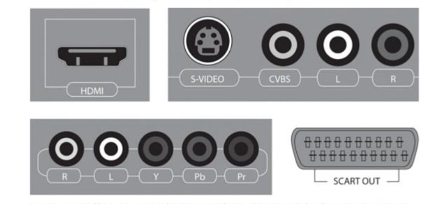
At this writing, the Apple TV comes with only an High-Definition Multimedia Interface (HDMI) port for output. This is great for new and newish TVs that have one or more HDMI ports. However, if you have an older TV that donesn’t have an HDMI port, you need to get a converter cable or adapter. Take a few minutes to look at your TV’s documentation to find out which connections it suppports. If you can’t find the documentation, look at the TV itself. Figure 1.2 shows the four main types of connection: HDMI, Component Video, Composite Video, and SCART.

HDMI

Using an HDMI cable for an HDTV

For an HDTV, you normally need only an HDMI cable. If you already have a suitable HDMI cable, you’re all set. If not, you can pick one up from most any store that carries electrical goods.

When you’re choosing an HDMI cable, consider the following:

HDMI logo: Make sure that the cable carries the HDMI logo, as shown in Figure 1.3. This means that the cable was tested and approved by the HDMI Organization ― the body responsible for setting and maintaing the HDMI standard. HDMI-approved cables cost a few dollars more than those that are unapproved, but you can be confident that they are of acceptable quality.

Length: If you can position your Apple TV near your TV, a three-or six-foot cable may be long enough. If the Apple TV needs to be farther away ― get a longer cable. Extremely long cables can cause signal problems (see the sidebar about HDMI cable length), so don’t buy one that is longer than you actually need.

Cost. Expect to pay between $10 and $20 for a quality HDMI cable of standard length (3 to 10 feet). Audiovisual specialists make and sell extremely expensive HDMI cables, and some cost thousands of dollars. Current expert opinion, though, is that basic HDMI cables are fine as long as they are properly make and you don’t mistreat them.

HDMI Standards. Some manufactures advertise their cables as being compliant with different standards, such as HDMI 1.2 and HDMI 1.3. HDMI 1.3 supports Deep Color, a feature that uses extra colors to give a richer display, automatic lip-synching, and high-resolution soundtracks, including Dolby TrueHD. At this writing, the Apple TV doesn’t use these features, so you don’t need HDMI 1.3 cables. If you can choose between an HDMI 1.2 or 1.3 cables. If you can choose between an HDMI 1.2 or 1.3 cable, go for the 1.3 for future compatibility.

Using a component or composite video converter

If you have a standard TV rather than an HDTV, you most likely need to use a Component Video input or Composite Video input instead of an HDMI input. If your TV provides both types of connections, use Component Video, because it gives higher quality. If your TV has only one type of connection, you’re stuck with that type.

HDMI Converter

How Long Can an HDMI Cable Be?

Unlike many other audio-visual specifications, the HDMI specification doesn’t get a strong enougth signal to produce a good picture.

If the HDMI cable is too long or damaged, you may notice the follwing symptoms:

● Distortion in the picture.
● Single pixels failing to appear in the correct color.
● No video at all, even though the audio plays correctly.

If you need to run the HDMI cable a long distance and find these symptoms appearing, get an HDMI signal restorer to strengthen the signal.

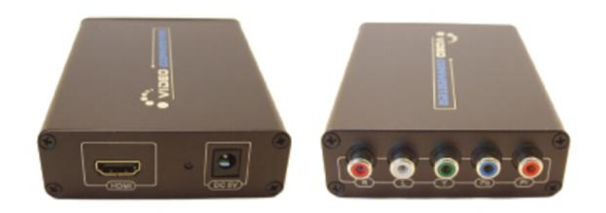
If your TV has a Component Video input, get an HDMI-to-Component Video converter like the one shown in Figure 1.4. This  HDMI video multiplexer is small box with an HDMI input at one end, as shown on the left in Figure 1.4, and a Component Video output at the other, as shown on the right in Figure 1.4. You also need a Component Video cable if you don’t already have one.

If your TV has a Composite Video input, you can get an HDMI-to-Composite Video converter. Similar to the Component Video converter, this is a small box with an HDMI input at one end, as shown on the left in Figure 1.5, and a Conposite Video output at the other, as shown on the right in Figure 1.5. You also need a Composite Video cable to connect the converter to your TV’s input.

Related Article:  Which Patch Cable Should I Choose for My Optical Transceiver?
                  

HDMI Extender (Optical Use) About Chromecast

Share

The HDMI Extender is also optional, and helps you connect the Chromecast even if does not plug directly into your television. It is, by all accounts, an extension. That is to say, if you cannot reach the back of your television (if it is mounted to the wall, perhaps), the extension will give you the room you need to still use the device. It may also improve your Wi-Fi reception, so hang onto it in case your television prompts you to use it during set up. If you do need it, coonect the HDMI video multiplexer into the television first, and then plug the Chromecast into the extender. This will keep you from damaging the small device before you even get to use it!

There is a small instruction manual that comes in the box as well. Small describes this instructional sheet perfectly because it appears to have been designed and printed for a baby doll to read. It is so tiny, in fact, that it is hard to turn the pages without feeling silly. The good news is, the Chromecast is simplicity as its best, so the manual isn’t really necessary. But it is cute.

You should already have some sort of television or display monitor which has an available HDMI port to plug the Chromecast into. If it has a USB port, that’s also helpful for plugging in the micro-USB power cable to. If your TV doesn’t have the USB port, don’t worry, you can plug the micro-USB cable (included) into the included USB/AC power adapater, and then plug that into a nearby wall outlet.

You’ll want to have a wireless network set up in your home (with a wireless modern and possibly a wireless router). If you have a secure wireless network, make sure you have any password or other info handy to enter for the Chromecast setup.

For streaming content to your Chromecast on your TV or monitor, you’ll need a Mac, Windows or Chromebook Pixel computer.

Additionally, you can use an Android or iOS smartphone or tablet. At this time, only certain apps will work on the mobile devices for streaming content. These include YouTube and Netflix, which you’ll be able to use. In the future, there is very likely to be more apps developed that will allow you to use the Chromecast streaming to your TV.

Video Extender is a kind of hardware devices that allow users to convert video in one signal format into another. For example, the video Extender built by Fiberstore provide simple plug-and-play operation, and include SDI Extenders, HDMI Extenders, VGA Extenders and DVI Extenders. This series of devices enables users to link previous technology formats with the newest updates without requiring a complete overhaul of their audio/video system. S-Video, Composite, Components, Coaxial and RGB Video Extenders. Wide screen video formats are supported, as well. These devices can be used when users to convert a video signal from some devices such as camera, notebook computer to a television. Next we will explain these video Extenders over fibers in detail.

Some Knoweledge About Erbium-droped Fiber Amplifer

Share

The eribum-doped fiber amplifier (EDFA) was first reported in 1987, and, in the short period since then, its applications have transformed the optical communications industry. Before the advent of optical amplifers, optical transmission systems typically consisted of a digital transmitter and a receivere separated by spans of transmission optical fiber intersersed with optoelectronic regenerators. The optoelectronic regenerators corrected attenuation, dispersion, and other transmission degradations of the optical signal by detecting the attenuated and distorted data pulses, electronically reconstituting them, and then optically transmitting the regenerated data into the next transmission span.

The EDFA is an optical amplifer that faithfully amplifies lightwave signals purely in the optical domain. EDFAs have several potential functions in optical fiber transmission systems. They can be used as power amplifiers to boost transmitter power, as repeaters or in-line amplifiers to increase system reach, or as preamplifiers to enhance receiver sensitivity. The most far-reaching impact of EDFAs has resulted from their use as repeaters in place of conventional optoelectronic regenerators to compensate for transmission loss and extend the span between digital terminals. Used as a repeater, the optical amplifier offers the possibility of transforming the optical transmission line into a transparent optical pipeline that will support signals independent of their modulation format or their channel data rate. Additionally, optical amplifiers support the use of wavelenth division multiplexing (WDM), whereby signals of different wavelengths are combined and transmitted together on the same transmission fiber.

In fiber optic systems amplification of the signal is necessary because no fiber material is absolutely transparent. This causes the infrared light (usually around 1530nm) carried by a fiber to be attenuated as it travels through the material. Because of this attenuation, repeaters must be used in spans of optical fiber longer than approximately 100 kilometers.

The operating wavelength range of a standard EDFA spans over the entire so-called “C band” (1530 to 1560 nm) and therefore allows amplification of a variety of wavelength channels that are used in wave-length division multiplexing (WDM)applications. This is a major advantage over methods in which the optical signal is converted into an electrical signal, amplified and converted back to light. Due to the last step, such O/E-E/O regenerators require the demultiplexing and multiplexing of each single WDM channel at each regenerator site and an O/E-E/O pair for each channel.

EDFA Configurations

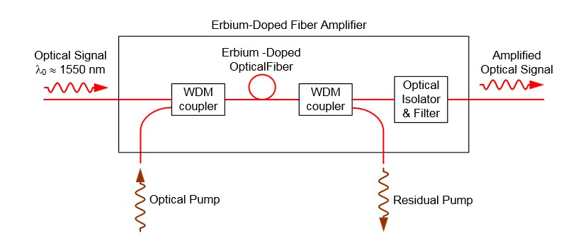
The configuration of a co-propagating EDFA is shown in Figure 5. The optical pump is combined with the optical signal into the erbium-doped fiber with a wavelength division multiplexer. A second multiplexer removes residual pump light from the fiber. An in-line optical filter provides additional insurance that pump light does not reach the output of the optical amplifiers. An optical isolator is used to prevent reflected light from other portions of the optical system from entering the amplifier.

fiber optic amplifer

Figure 5. An EDFA for which the optical signal and optical pump are co-propagating.

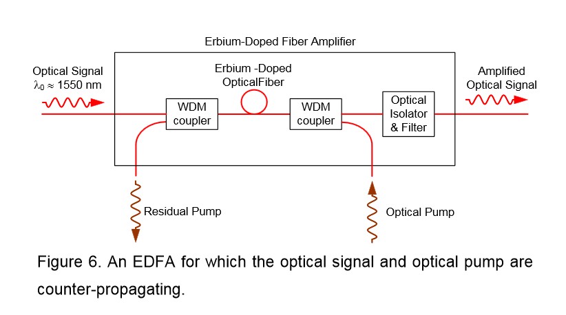
An EDFA with a counter propagating pump is pictured in Figure 6. The co-propagating geometry produces an amplifier with less noise and less output power. The counter propagating geometry produces a noisier amplifier with high output power. A compromise can be made by combining the co- and counter-propagating geometries in a bi-directional configuration.

EDFA Amplifer

The propagation and amplification properties of an erbium-doped fiber at 1550 nm are obtained. A simple EDFA is constructed, and its performance is tested. A small signal with wavelength of 1530 nm can be amplified with amplification up to 14 dB/m and SNR of 18.8, if a pumping laser of wavelength 980 nm and driving current 400 mA is used. A higher amplification is expected if a more intense pumping laser is supplied. The erbium doped fiber amplifier proves efficient and concise in amplifying signals around 1550 nm.

FBG Sensor Multiplexing Techniques On WDM System

Share

Fiber Bragg Grating (FBG) is a simple and low-cost filter built into the core of a wavelength-specific fiber cable. FBGs are used as inline optical filters to block certain wavelengths, or as wavelength-specific reflectors.

In many applications a large number of sensors need to be used to achieve a distributed measurement of the parameters. In particular, using sensors in smart structures is of interest where sensor arrays are bonded or embedded into the materials to monitor the health of the structure. FBG sensors have a distinct advantage over other sensors because they are simple, intrinsic sensing elements that can be written into a fiber, and many sensors can be interrogated through a single fiber.

The most straightforward multiplexing technique for FBG sensors is wavelength division multiplexing (WDM), utilizing the wavelength-encording feature of an FBG-based sensor. The WDM technique is based on spectral splicing of an available source specturm. Each FBG sensor can be encoded with a unique wavelength along a single fiber. Since we are operating in the wavelength domain, the physical spacing between FBG sensors can be as short as desired to give accurate distributed information of measurands.

A parallel topology is used to allow simultaneous interrogation of all the sensors in WDM, as shown in Figure 4.15. A1 x N fiber optic splitter is used to divide the optical reflection into N channels, In each channel a matched fiber grating detects the wavelength shift from a specific FBG sensor.

Fiber splitter

In the parallel scheme each filter receives less than 1/2N of optical power as a result of using 1 x N fiber splitter and fiber coupler. More FBG sensors lead to a larger power penalty. An improved scheme using a serial matched FBG array is reported by Brady et al, as shown in Figure 4.15(b). This scheme is claimed to allow the optical power to be used more efficently than in the parallel topology. As can be seen, however, a large power penalty still exists through the use of the reflection of matched fiber gratings. A revised verison of the serial scheme is proposed, in which the transmisson of the matched FBG is used to monitor the wavelength shift from the corresponding sensing FBG. This reduces the power penalty of 6 dB.

Several Digital Video Multiplexers Types from FiberStore

Share

As we know, a fiber optic multiplexer is a device that processes two or more light signals through a single optical fiber. It is introduced as an effective solutions to a fiber’s transmission capacity using different techniques and light source technologies. By using a multiplexer, media or data signals can be forwarded further, more securely with less electromagnetic and radio frequency interference.

The so called WDM (Wavelength Division Multiplexing) utilizes the total available pass band of an optical fiber. It assigns individual information streams into separate wavelengths, or portion of the electromagnetic spectrum. Frequency and wavelengths can be regarded as the same concept. The only difference is the frequency is typically used to describe the radio carriers. Frequency division multiplexing assigns each signal a distinctive frequency.

Digital video multiplexer is a typical fiber optic multiplexing devices for video and data signal’s fiber optic transmission. Digital video technology emerged as the ultimate facilitator of surveillance needs and has played an important role in the security area, that enables flexible, real-time, highly manageable and tunable solutions. Digital video multiplexer combined with this one-up digital uncompressed technology with WDM technology, make it possible to extend video and data service up to 100km distance simultaneously through one single fiber, and get the real-time high-definition video on the receiver side. This device is usually used for security application to control and monitor video cameras signals in airports, train station and public hotspots.

FiberStore fiber optic digital video multiplexer adopt the advanced international digital video and coarse wavelength division multiplexing (CWDM) technology, these multiplexers can transmit from 1 channel video & audio & data channel to max 64 channel signals in different optical distances. These video multiplexer are single mode and multimode fiber type with multichannel track mount or standard units. Insert card version is also available, which can be inserted into our 16-slot, 19inch 2U or 4U rack-mountable card cage for 10-digit coding and non-compression video transmission. Typical fiber ports of these multiplexer are FC, SC or ST, interfaces are RS232, RS422 or RS485, which can be customized by users for actual demand.

Now, in the following text, let’s overview FiberStore four types of digital video multiplexers: Video multiplexers, video & audio multiplexers, video & data multiplexers, video & audio & data multiplexers.

1-64 Channel Video Multiplexers

Video multiplexers are built on Coarse wavelength division multiplexing (CWDM) and can encodes multi-channels video signals and convert them to optical signals to transmit on optical fibers. It handled several video signals simultaneously, and can also provide simultaneous display and playback features. We provide video multiplexers in different channels such as 1, 2, 4, 8, 16, 24, 32, 64 channels. They are available in both color and black and white video multiplexers, digital video multiplexers and processors. With a video multiplexer, users can record their combined signals on the VCR or wherever else they want to record. Our video multiplexer help users built a cost effective network system with the best process control and quality assurance.

Digital multiplexer has two VCR IN connections and two VCR OUT connections. There is one pair of VCR IN/OUT 4-pin DINI connectors (Y/C) and one couple with BNC connections (composite video). The VCR IN connectors is used to connect the multiplexer to a VCR which will be used to playback recorded images. Connect the Video OUT connector on a VCR to one of the VCR IN connectors on the multiplexer. The VCR OUT connectors are used to connect the digital multiplexer to a VCR which will be used to record video. Connect the Video IN connector on a VCR to one of the VCR OUT connectors on the multiplexer.

Video Data Multiplexers
Video data multiplexers are based on digital video technology to provide fiber optic transmission of video and return or bidirectional data signals in demanding environments. They can provide highly reliable data transmission and expandable data capacity over fiber optic cables up to a few tens of kilometers. The video data multiplexers simultaneously transmit multi-channel 8-bit digitally encoded broadcast quality video over one multimode or single mode optical fiber.

This module is directly compatible with NTSC, AL, or SECAM CCTV camera systems and support RS-485, RS-422, and RS-232 data protocols. These muxes are typically used with cameras that have PTZ capability. The plug and play design ensures adjustment-free installation and operation. LED indicators are provided for instant monitoring system status.

We supply video & data multiplexer in channels includes 1, 2, 4, 8, 16, 24, 32 channel. Typical installation utilizes the transmitter unit at the camera end of the link, and connects via a single fiber optic cable, to a receiver unit at the monitoring end of the link. These Video & Data multiplexers are suitable for concentration management in 1U/2U/4U Racks, and we also can supply the rack chassis for you.

Video & Audio Multiplexers
Video and Audio Multiplexer combines digital video with digital audio to form the embedded signal. It has optical remote monitoring capabilities so that operation can be controlled remotely. The audio video multiplexer can simultaneously transmit 1-64 channels of 8-bit digital encoded broadcast quality video/unidirectional or bidirectional audio signals over multimode or single mode optical fiber. These multiplexers are used in applications where the cameras have P/T/Z capabilities.

We supply video & Audio multiplexer in different channels such as 1, 2, 4, 16 channels, they are ideal for applications of security monitoring and control, highway, electronic policy, automation, intelligent residential districts and so on.

Video & Audio & Data Multiplexers
Video & Audio & Data Multiplexers transmit 1-64 channels of 8-bit digitally encoded broadcast quality video / return or bidirectional data / unidirectional or bidirectional audio over one multimode or single-mode optical fiber. These multiplexers are used in applications where the cameras have P/T/Z capabilities. With Plug and Play design, it can convert, integrate, groom and multiplex multiple video/audio/data streams effortlessly.

The Video & Data & Audio Multiplexers are ideal for a wide range of multiplexing and remultiplexing applications including Broadcast /Studio, CCTV audio and Professional AV applications.

FiberStore is a leading global supplier of telecommunications solutions for the electric utility, pipeline, transportation and industrial applications. This powerful family of optical multiplexers permits consolidation of all telecommunications requirements into a single, integrated network.

Erbium-Doped Fiber Amplifier for DWDM Systems

Share

DWDM EDFA (Erbium-Doped Fiber Amplifier) is a key component in DWDM network systems. It uses an optical supervisory channel power adjustment and extends the power link budget for long distance DWDM communication systems. As the operating bandwidth of the EDFA has 30nm, it can zoom back of a plurality of different wavelength optical signals, and so it can be very conveniently used in DWDM systems to compensate for various optical attenuation.
With gain flattening filter, DWDM EDFA offers constant flat gain for multi-channel DWDM systems. It works at C-band or L-band, integrates electric driver, remote control, temperature control, and alarm circuits all together in a small package. It has assembled up to three pump lasers to meet the different output power levels required by DWDM systems and protect the pump failure.

FiberStore provides 40 channel BA Module DWDM EDFA. This product is spectrum flat EDFA for DWDM system. It offers high optical gain, low noise figure and high saturation optical power which are fully integrated with various kinds of DWDM systems. This DWDM EDFA has perfect network interfaces including one Ethernet RJ45 port, one RS232 port and two RS485 ports. And the open mib ensure the connectivity with all other network management system. Click here for the DWDM EDFA price.


FiberStore DWDM EDFA Features

1. Low noise figure with typical 4.5dB and high flatness with typical 1dB

2. Covers whole C-band and carries 40 or 80 channels

3. Redundancy hot swap power module with 110/220V AC and 48V DC can plug mix

5. Supports telnet and SNMP network management

6. Gain can be adjustable by network and manual

7. High precise AGC (automatic gain control) and ATC (automatic temperature control) circuits
8. High saturation output power

9. Flexible mechanics and circuit structures (Module, 1U Rack and Gain Block)

10. OEM is available and fully compatible with Telecordia GR-1312-CORE

FiberStore DWDM EDFA Functions

1. A 5V OLT 25W ATT power supply with input protection and output filtering. It is necessary to monitor the current supplied to the EDFA (this gives a measure of the aging of the device) and desirable to monitor the voltage.

2. Drive two digital input lines which control the gain of the DWDM EDFA.

3. Monitor two analog outputs which measure the input and output optical amplifier power levels.

4. Communicate with the EDFA serial port which is RS232 protocol but at TTL levels. (This allows more detailed health monitoring and setting of operating conditions that is possible using only the digital signals.)

5. Communicate with a LMA monitor and control bus. The controller is a circuit card 40mm wide by 220mm high.

CWDM Technology VS DWDM Technology

Share

WDM is a technology that is achieved using a multiplexer to combine wavelengths traveling through different fibers into a single fiber. The space between the individual wavelengths transmitted through the same fiber are the basis for differentiating the CWDM and DWDM.

CWDM- Coarse wavelength division multiplexing. WDM systems with fewer than eight active wavelengths per fiber. DWDM – Dense wavelength division multiplexing. WDM systems with more than eight active wavelengths per fiber.

CWDM is defined by wavelengths. DWDM is defined in terms of frequencies. DWDM’s tighter wavelength spacing fit more channels onto a single fiber, but cost more to implement and operate. CWDM match the basic capacities of DWDM but at lower capacity and lower cost. CWDM enable carriers to respond flexibly to divers customers needs in metropolitan regions where fiber may be at a premium. The point and purpose of CWDM is short-range communications. It uses wide-range frequencies and spreads wavelengths far apart from each other. DWDM is designed for long-haul transmission where wavelengths are packed tightly together. Vendors have found various techniques for cramming 32, 64, or 128 wavelengths into a fiber. DWDM system is boosted by Erbium-Doped Fiber Amplifier, so that to work over thousands of kilometers for high-speed communications.

Hardware Cost
The cost difference between CWDM and DWDM systems can be attributed to hardware and operational costs. Despite the superiority in terms of cost of DWDM laser with respect to the CWDM DFB laser chilled provide cost effective solutions for long haul and metro rings large capacity demanding. In both applications, the cost of DWDM system is set off by the large number of customers who use this system. Except for encapsulation, the DWDM laser for stabilizing the temperature with a cooler and a thermistor, it is more costly than an uncooled laser coaxial CWDM.

Power Consumption
The energy requirements for DWDM are significantly higher. For example:DWDM laser temperature stabilized through coolers integrated modules encapsulation, These devices together with the associated PIN and the control circuit consumes approximately 4 W of power per wavelength monitor. However, an uncooled CWDM laser transmitter consumers about 0.5w. The transmitter of 8 channel CWDM system consume about 4W of power, while the same functionality in a DWDM system can consume up to 30W. As the number of wavelengths in DWDM systems with increased transmission speed, power and thermal management associated with them becomes a critical issue for the designers.

Because DWDM doesn’t span long distance as its light signal isn’t amplified, which keeps costs down but also limits maximum propagation distances. Manufacturers may cite working ranges of 50 to 80 kilometers, and by signal amplifiers to achieve 160 kilometer. CWDM supports fewer channels and that may be adequate for carrier who would like to start small but expand later when demand increases.

Related article: How to Install Your CWDM MUX/DEMUX System?

Fiber Optical Multiplexers Catalog Introduction of FiberStore

Share

FiberStore is a company that have rich experience in producing and developing fiber optic multiplexer systems, and have several successful commercial product lines for video/data multiplexing in Remotely Operated Vehicles (ROVs). FiberStore optical multiplexers are designed to provide reliable fiber optic transmission of video, audio and data signals in the demanding subsea applications, robust defense systems and other platforms operating in a harsh environments.

Fiber multiplexer is powerful communications equipment. They allow mixing of T1/E1, Ethernet, POTS ports (FXO or FXS) and serial datacom interfaces such as V.35, RS-232, X.21 etc. Together on a single circuit of fiber optic, so that fiber is saved and higher density and capacity networks can be put together. FiberStore multiplexers are supported by industry leadership in fiber optic development, including optical sensors, telemetry systems, connector design, ruggedized optics, and the widest selection of Fiber Optic Rotary Joints (FORJs). All of these fiber optic multiplexers supports remote management and have optional service line ports. Capacity starts with 4T1 or E1 interfaces on low entry models and goes up to 63T1Ss or E1s together on a single strand of fiber optic cable.

Typical optical multiplexers are Video & Data & Audio Multiplexers, PDH Multiplexer. Custom solutions provide support for additional signal formats or unique combinations of standard protocols. Application specific products can be also customized to reduce size or cost, optimize packaging, extend environmental performance, and integrate more directly with other equipment.

Video Multiplexers
Video multiplexer is used to encodes the multi channel video signals and convert them to optical signals to transmit on optical fibers. It handles several video signals simultaneously and it can also provide simultaneous playback features. With the video multiplexer, you can record the combined signal on your VCR or wherever else you want to record.

Video & Data Multiplexers
FiberStore video & data multiplexers provide high reliable fiber optic transmission of video and data signals in demanding environments. A wide range of supported video and data formats ensure the flexibility needed for easy system configuration. Individual data channels can be mixed and matched with a variety of plug-in interface modules. Advanced optical multiplexing (CWDM, DWDM) enables system expansion to 32 video and 256 data channels as well as additional high data rate signal such as HD-SDI, ECL for advanced sonars, and Gigabit Ethernet.

Video & Audio Multiplexers
Video and audio multiplexer combines digital video with digital audio from the embedded signals. It has optional remote monitoring capabilities so that operation can be monitored remotely. Video & Audio Multiplexer is widely used in security monitoring and control, high way, electronic police, automation, intelligent residential districts and so on.

Video & Data & Audio Multiplexers
Video/data/audio multiplexers are designed for users to convert, integrate, groom and multiple video/audio/data streams effortlessly. These multiplexers can transmit and extend a maximum of video, audio and data over fiber cables up to a few tens of kilometer. They are ideal for applications like Broadcast/Studio, CCTV audio and professional AV applications.

FiberStore now offer a full range of multiplexer products, from single channel media converters for Ethernet and HD-SDI to multi-channel CWDM and DWDM multiplexer supporting 16 or more video lines, 128 serial data channels, multiple digital I/O, plus 10/100/100M Ethernet and high bandwidth sonar interfaces, all on a single optical fiber.

Variable Optical Attenuator Description

Share

High intensity, coherent light beams are used as an increasingly common means of transmitting data. Optical fibers provide higher data rates with lower cost, weight and volume per units of length than cables relying on metallic conductors.

A variety of devices are known for controlling the light beam. Once of these is the fibre attenuator.

An exemplary optical attenuator is described and shown in U.S. NO. 4,192,573 to Brown, Jr.ct al. A flat mirror reflects an input beam of light. A focusing mirror receives the beam of light reflected from the flat mirror, so that the axis of the beam of light reflected by the focusing mirror is offset from and, parallel to, the axis of the input beam of light. A pinhole assembly receives the beam of light reflected from the focusing mirror. The pinhole assembly has a pinhole positioned on the axis of the beam of light reflected by the focusing mirror. A servo-motor actuates the flat mirror and the focusing mirror, in unison, relative to the pinhole assembly in a direction parallel to the axis of the input beam of light. The parallel movement of the mirror acts to vary the proportion of the input beam of light that passes through the pinhole. The servo mechanism is bulky and requires a relatively long period of time to move the mirrors relative to the pinhole assembly.

The present invention is a variable optical attenuator (VOA) which has a semiconductor micro-electro-mechanical device for positioning a reflecting surface in any of a plurality of positions, each providing a respectively different amount of attenuation.

The variable optical attenuator includes a Icns, a first optical waveguide, and a second optical waveguide. A semiconductor micro-electro-mechanical device is positioned on a side of the lens opposite the first and second optical waveguides. The device has a reflecting surface. The reflecting surface has a normal position in which light from the first waveguide reflects off of the reflecting surface and passes through the lens into the second waveguide. The reflecting surface has a plurality of respectively different attenuation positions in which light from the first waveguide reflects off of the reflecting surface and passes through the lens, but an amount of light entering the second optical waveguide is attenuated by respectively different amounts corresponding to the respectively different positions.

According to a further aspect of the invention, a method for controlling a beam of light includes providing a lens, first and second optical waveguides, and a semiconductor micro-electro-mechanical device positioned on a side of the lens opposite the first and second optical waveguides. The devices having a reflecting surface. The reflecting surface is pivoted to a normal position in which light from the first waveguide reflects off of the reflecting surface and passes through the lens into the second waveguide. The reflecting surface is pivoted to a plurality of respectively different attenuating positions in which light from the first waveguide reflects off of the reflecting surface and passes through the lens, but an amount of light entering the second optical waveguide is attenuated by respectively different amounts corresponding to the respectively different positions.