In most terrible building or house fire disasters, combustible plastics (PVC) used in the wiring are always among the very things that contribute to the rapid spread of fire and toxic smoke. And the air conditioning systems even help the toxic smoke given off by the burning cables to spread throughout the building quickly. As for the high density data center with high speed computing equipment and large amount of plastic jacketed cables, it is crucial to take measures to reduce the damage in an unwanted fire. How to make the crucial data center a safer place? The high quality plenum cable (eg. MTP fiber) can be one of the best choices.
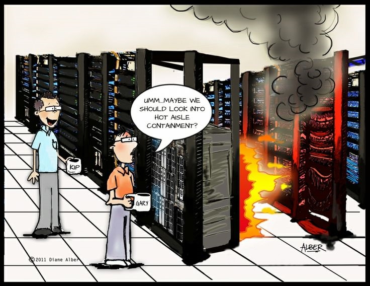
The break-down of precision air conditioning system might lead to fire incident.
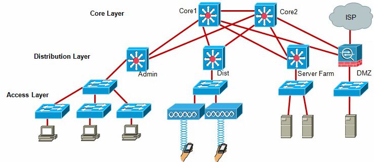
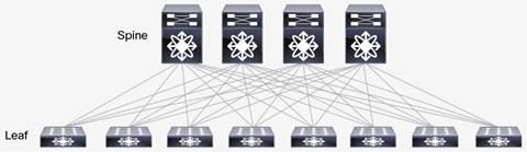
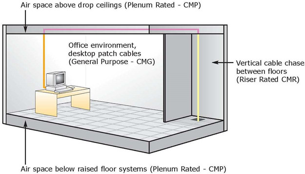
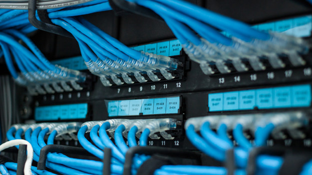
Plenum space is an area used for return of air circulation or air conditioning systems. In a data center, the spaces covered by the precision air conditioning unit are often necessary to deploy plenum products. They include not only plenum containment that separates cold aisle and hot aisle, but also plenum cables that meet the highest fire code requirements. Both electric cables and fiber optic cables are required to be plenum rated (CMP) when they are installed in inner walls and inner ceilings of data center buildings.
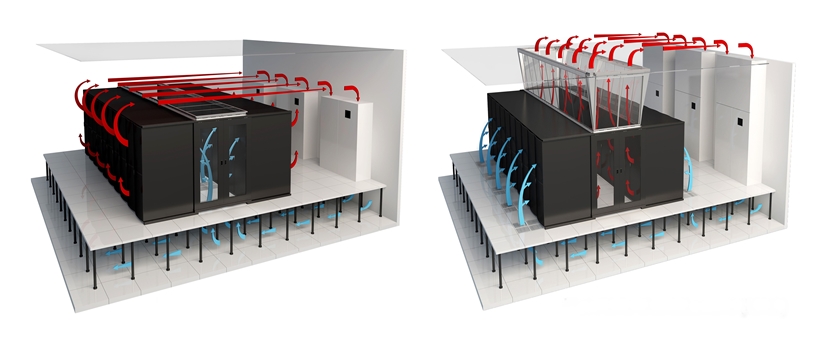
Cold aisle containment (left) and hot aisle containment (right) in a precision air conditioning unit.
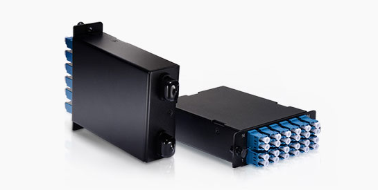
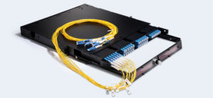
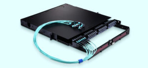
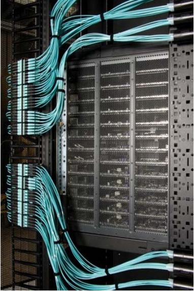
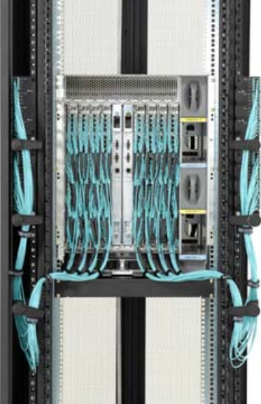
The integration of plenum jacket and MTP fiber is a perfect solution for high density data center applications. The safety feature of the plenum cable and the high fiber port count of MTP connector endow the data center with two essential components. By using MTP plenum cable, the possible danger that might be caused by cables located at cold aisle and hot aisle can be minimized when a fire incident occurs. In addition, the high bandwidth demands within a limited space in data center can be satisfied.
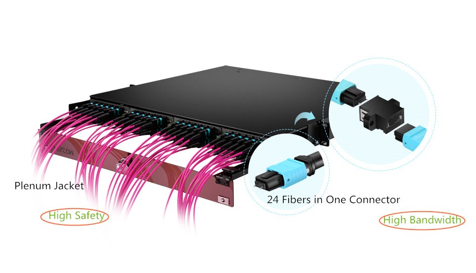
Use MTP plenum cable to get safety and high bandwidth at the same time.
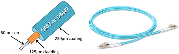
When buying MTP fibers, be sure to check if it is genuine plenum rated and the MTP connector should meet the physical connection standard for acceptable insertion loss. When burnt, plenum cable will give off little smoke, and the color of the smoke is light instead of dark. FS MTP plenum cables are made of Corning fiber and U.S. Conec MTP connector. They are all tested and guaranteed by 3D interferometry and the insertion loss is no more than 0.35 dB. No matter it is the plenum jacket, the inner fiber, the connector, or the end face geometry, they are all genuine parts and in high quality. They can be checked by any user without a problem.
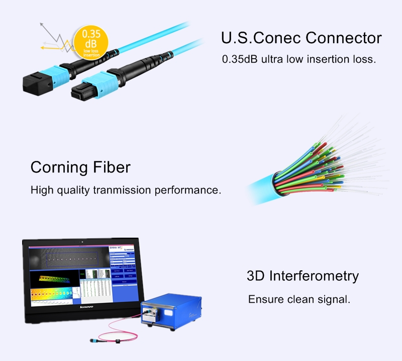
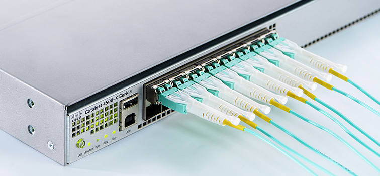
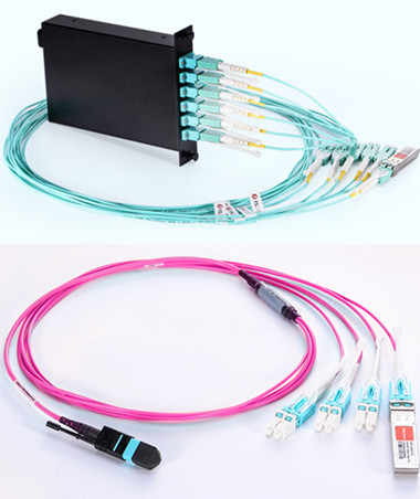
FS high quality MTP plenum cable made of U.S. Conec connector and Corning fiber.