Category Archives: Fiber Patch Cord

Understanding Optical Fiber Cable Fire Ratings

Share

As we all know, optical fiber cables shall be listed as suitable for the purpose. Cable usually be marked in accordance with NEC (National Electrical Code) Table 770.19. Most manufacturers put the marking on the optical fiber cable jacket every 2′ to 4′. The code does not tell you what type of cable to use (such as single-mode or multi-mode). In fact, It tells you this cable can be resistant to the spread of fire. This text will introduce the knowledge of optical fiber cable fire ratings and help you choose the right fiber for your applications.

Types of Fire-proof Optical Fiber Cable

There are three kinds of cable jacket fire ratings: plenum, riser and general purpose. Plenum cables are held to the most stringent testing of any of the cables rated by the NEC, rated for both flammability and smoke generation. Riser cables are subjected to flame tests only, and are not held to as high of a standard as Plenum rated cables. General Purpose cables may be used anywhere in commercial buildings other than areas where Riser or Plenum cables are required. Besides, optical fiber cable can be divided into nonconductive and conductive according to NEC. Nonconductive cables contain nothing that can conduct electricity, so will not accidentally energize or be energized even when closely associated with electrical conductors. Conductive cables contain noncurrent-carrying conductive members such as metallic strength members, metallic vapor barriers and metallic armor or sheath. Therefore, according to these three cable jackets and whether the cable is nonconductive or conductive, these fire-proof optical fiber cables can be divided into following several types.

Cable Marking Type
OFNP Nonconductive optical fiber plenum cable
OFCP Conductive optical fiber plenum cable
OFNR Nonconductive optical fiber riser cable
OFCR Conductive optical fiber riser cable
OFNG/OFN Nonconductive optical fiber general-purpose cable
OFCG/OFC Conductive optical fiber general-purpose cable

Optical Fiber Cable Fire Ratings

There are three levels of fire resistance in terms of optical fiber cables. The ratings are hierarchical. For example, from a fire resistance standpoint, a higher rating can be substituted for any lower rating, but not vice versa. Also, nonconductive may be substituted for conductive, but not vice versa. The fire ratings of optical fiber are showed below, from most stringent to least.optical fiber cable fire ratings

Choosing the Right Fiber for Your Application

In terms of different cable fire ratings, there are different kinds of optical fiber cables. So choosing the right one becomes a difficult problem. Usually, for those planning or installing a fiber network, the key point of UL 1651 is to help ensure you select the right fiber for your particular need. These are described in article 770.19 of the NEC, but here are some common measures:

  • For a small, in-building deployment, using a riser – OFNP, OFCP, OFNR, OFCR,OFNG, OFCG, OFN, OFC
  • Within an existing, fabricated duct inside a building – OFNP, OFCP
  • In a plenum space that is used for environmental air inside a public building – OFNP, OFCP
  • Inside a fireproof shaft using a riser within any type of building – OFNP, OFCP, OFNR, OFCR,OFNG, OFCG, OFN, OFC
  • When using a metal raceway for in-building deployments covering multiple floors and rooms/apartments – OFNP, OFCP, OFNR, OFCR,OFNG, OFCG, OFN, OFC
  • For vertical runs between floors within a riser – OFNP, OFCP, OFNR, OFCR
  • Within a riser cable routing assembly inside a building – OFNP, OFCP, OFNR, OFCR
  • For in-building deployments with routing only on 1 floor – OFNP, OFCP, OFNR, OFCR,OFNG, OFCG, OFN, OFC

Related Article: Understanding Fiber Optic Cable Jacket & Fire Rating

OFNP: Optical Fiber Nonconductive Plenum Cable

Share

With the wide use of optical fiber cables, more and more people show their interests in plenum fiber optic cable, which is also called OFNP cable. In order to learn about this cable, first of all the meaning of the word “plenum” will be explained. And then we may introduce what the plenum fiber optic cable is. At last, applications of the OFNP cable will be described.

What does a Plenum Area Mean?

A Plenum area is a building space used for air flow or air distribution system. In most buildings, the area above a drop ceiling or under a raised floor is used as the air return (source of air) for the air conditioning. Those drop ceiling and raised floors are also where fiber cables are often installed. The concern is that during a fire, if there is burning material in a plenum air space, smoke and fumes can travel through air ducts to the whole building. For this reason, there are codes to restrict the types of materials (such as cables) that can be placed in the plenum.

8

In terms of plenum fiber cables, the plenum refers to a cable jacket. National Electrical Code (NEC) requires indoor fiber optic cables be marked with their fire and smoking ratings. According to NEC, a building’s inside area is divided into three types of sections: plenums, risers and general purpose areas. So there are three types of cable jacket in all: plenum, riser, and general purpose. Among plenum cables are held to the most stringent testing of any of the cables rated by the NEC, rated for both flammability and smoke generation.

What is a Plenum (OFNP) Fiber Cable?

7OFNP stands for Optical Fiber Nonconductive Plenum. OFNP is the designation given by the National Fire Protection Association (NFPA) to interior fiber optic cables which contain no electrically conductive component, and which are certified for use in plenum applications. They are engineered to prevent the spread of fire from floor to floor in a building. It is generally intended for horizontal runs especially within an air handing conduit. This type of cable complies with the Underwriters Laboratories (UL) fire safety test Plenum/910. They can be installed in ducts, plenums and other spaces used for building airflow. This is the highest fire rating fiber cable and can’t be replaced with any other cable type.

Plenum (OFNP) Fiber Cable Solutions

Since plenum cables are routed through air circulation spaces, which contain very few fire barriers, they need to be coated in flame-retardant, low smoke materials. These materials offer good resistance against possible fire, so plenum (OFNP) fiber cables have fire-resistance and low smoke production characteristics. And even if in the event that they do begin to burn, they will not emit large quantities of harmful fumes. For these reasons, these plenum fiber cables provide a low cost option for gigabit Ethernet network applications and are used for running in walls and air plenums without the use of conduit. If you want to buy this kind of effective cable, I recommend you to visit Fiberstore, which offers fully typed OFNP fiber patch cables (SC, FC, LC, ST, MU, MTRJ, E2000, MTP etc) at only 3 dollars each.

One Small Problem When We Choose the Fiber Patch Cable

Share

There is a common phenomenon that people are always able to distinguish different types of interfaces easily after corresponding to the given pictures, but when we choose the fiber patch cable, such as the polishing type also confused them, it shows UPC or APC, also confused us, recently I finally understand it and share my ideas with you.

First we can look from the definition, the above are acronyms for the following:

    • UPC – Ultra Physical Contact
    • APC – Angled Physical Contact

Only from the words we can have a simple understanding of them, in order to have a deeper understanding, there i named a few examples for you. Usually when we hear about the description like “fiber patch lc apc lc upc”, “e2000 fc apc”, “sc apc to sc upc single mode 9 125 simplex fiber optic patch cord cable”, what do this words apc upc mean? Then we will give you explanations. In Fiberstore, We use different color to distinguish them, the blue is UPC connector and the green is APC connector, shown as the figure.

In fact, it stands for the polish style of fiber optic core and connect the copper connector of copper cable as medium, and we need to know that the connections between the fiber optic connector and the ceramic core. Different fiber optic connector ring’s size, length and polished style is different, different polish of the fiber optic connector rings result in different performance, mainly on the back reflection. Generally, UPC is 50dB or higher and APC is 60dB or higher. All insertion loss of that they should be less than 0.3dB and the lower insertion loss is, the better performance they have, it is the reason why UPC connector is more widespread than APC. At the same time, there is a point we need to pay attention to, we all know that fiber optic cables can be divided into single mode and multimode fiber cables, but single mode fiber optic cables can be with UPC or APC polished connectors, while multimode fibers are not made with APC connectors. When we talk about the insertion loss, fiber optic attenuators have to be mentioned, it also has the diffent db to choose, as for the more knowledge about it, please always pay close attention to.

Fiberstore, you know, it offers kinds of fiber cables to choose, the different connector series all available for UPC/APC version, and we can also provide SM, MM, OM3 cables, simplex and duplex option, 0.9mm, 2.0 mm, 3.0mm cable diameter for choose, as for the fiber length, it can be customized according to your requirements.

Related Article:  Which Patch Cable Should I Choose for My Optical Transceiver?

Two Main Connector Type: ST vs SC

Share

There are many different fiber optic connection methods, connector types, and ways to terminate them, such as SC connector and ST connector. Single-mode and multi-mode connectors create differences in the types and methods used as well. If you plan to work with fiber optics, you should perform in-depth research about fiber before attempting to terminate it. In fact, it is best to take a course in fiber optic cable termination or learn from an expert. This post will tell you how to choose  ST vs SC connector when terminating fiber and adding connectors.

In addition to the two main connector types of ST vs SC connector, there are many other connection types that have been developed through the years. But to limit the scope of this book to what is most widely used on data networks today, you need to be thoroughly familiar with the ST vs SC connectors.

ST vs SC Connector: Which to choose?

SC Connector

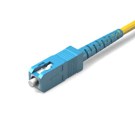
SC type connector is a snap-in connector, meaning that you place it in a receptacle, such as on a network switch, and click it into place; this is also called stick and click. The SC connector is shown in the figure below.

SC connector

SC connector is a relatively new connector-type technology, but are in popular use today. Part of their popularity is that SC connector is cheaper and easier to use than ST connectors, and less prone to damage. You will most likely see these types of connections from large core switches with fiber uplinks to smaller closet switches in campus network.

As we know, SC patch cable is with SC fiber connector which was invented by NTT. It is widely used fiber optic patch cables. SC fiber optic patch cable has low cost and good durability, SC fiber optic patch cables is with a locking tab on the cable termination, it is a push and pull type optical connector. The common SC patch cable we have seen, there are SC to FC, SC fiber optic cable, SC to ST, and SC to LC.

ST Connector

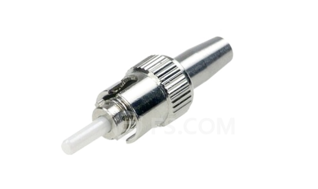
ST connector is another type of fiber connection. Like the BNC connector for coaxial cable, it has a bayonetbased mounting end and a long cylindrical ferrule, which is spring-loaded sheath used to hold the fiber in place. You insert the connector into a receptacle and twist it to lock it into place. Stick and twist considered an older technology, but is still widely used on data networks, and its install base is broad. An ST connector is shown in the figure below.

st-connector

Real-world production environments (especially when working with Cisco Systems, Nortel Networks) do not include ST in new implementations. In most cases, the only way to use this order technology is with a mediation device, such as a transceiver, which has one end that plugs into an attachment unit interface (AUI) port and an ST-based mounting connection on the other end.

Conclusion on ST vs SC Connector

To facilitate installation of our active fiber equipment, we support a large selection of fiber optic patch cords. The always in stock fiber cables are with SC connector, ST connector, LC connector and FC connector type, simplex and duplex. Our patch cords range from 0.5m to 10m and have almost all available combination of optical connectors. The most available lengths are 1m, 2m, 3m, 5m, and 10m patch cords. All single-mode patch cords are UPC polished (Ultra Physical Contact), while the multi-mode cables are PC polished. All fiber patch cords are manually tested and verified and each patch cable is individually sealed and labeled with measured optical performance.We offer competitive price for fiber optic patch cable, our company has strictly quality control system and high quality products,the custom fiber patch cable is fast delivery to worldwide customers.

Related Article:  Which Patch Cable Should I Choose for My Optical Transceiver?

                             How Many Fiber Connector Types Do You Know?

                             How Much Do You Know About Fiber Connector Cleaning? 


The Progress of Multimode Fiber

Share

In 1976, Corning developed 50/125μm by the graded-index multimode fiber and 1983 by Lucent Bell Labs developed 62.5/125μm graded-index multimode fiber, they are two larger amount of Multimode Fiber. The cladding diameter and mechanical properties of these two fibers are same, but different transmission characteristics. They can provide such as Ethernet, Token Ring and FDDI protocols specified in the standard distance required bandwidth, and it can be upgraded to Gb/s rate.

The new multimode fiber standard grades issued by ISO / IEC 11801, Multimode fiber is divided into four categories, OM1, OM2, OM3, OM4. OM1 and OM2 refer to traditional 62.5/125μm and 50/125μm multimode fiber. OM3 and OM4 refer to the new Gigabit 50/125μm multimode fiber.

62.5/125μm Graded-index Multimode fiber(OM1,OM2)

Common 62.5/125μm graded-index multimode fiber is the IEC-60793-2 fiber optic products specification Alb type. As the core diameter and a numerical aperture of 62.5/125μm fiber is greater, which has a strong anti-concentrating ability and bending characteristics, especially in the 20th century, before the mid-1990s, the lower the rate of the LAN, less demanding on the fiber bandwidth, thus making this fiber to obtain the most widely used, becomes 20 years between the mid-1980s to the mid-1990s mainstream products in most countries data communications fiber market. Belong OM1 and OM2 fiber types of Alb full power injection (OFL) bandwidth respectively 200/500MHz.km (850/1300nm) 500/500MHz.km (850/1300nm).

Now you can see the follow products about 62.5 Multimode Fiber

Duplex OM1 62.5/125 Dia2.5mm Fiber Patch Cable

SMA905- SMA905 Duplex OM1 62.5/125 Dia2.5mm Fiber Patch Cable from Fiberstore

50/125μm graded-index multimode fiber(OM1,OM2)

Common 50/125μm OM2 Fiber graded-index multimode fiber is the IEC-60793-2 fiber optic products specification Ala.1 type. Historically, in order to reduce as much as possible the cost of the LAN system, widely used inexpensive LED as the light source, rather than expensive LD. Since the LED output power is low, the divergence angle is much larger than LD, while the core diameter and a numerical aperture of 50/125μm multimode fiber are relatively small, is not conducive to efficient coupling with the LED, as large core diameter and numerical aperture of 62.5/125μm (Alb class) fiber enables more light power coupled into the fiber link to, therefore, 50/125μm graded-index multimode fiber in the mid-90s as good as 62.5/125μm (Alb class) that is widely used fiber.

Since the 20th century, a local area network developed up to lGb / s rate, it didn’t meet the requirement 62.5/125μm OM1 Fiber bandwidth with LED light source. Compared with 62.5/125μm multimode fiber, 50/125μm multimode fiber core diameter and a numerical aperture smaller, 50/125μm gradient in the number of multi-mode fiber conduction mode refractive index of about 62.5/125μm multimode fiber conduction mode 1/2.5, thus effectively reducing the modal dispersion of a multimode optical fiber, such that the bandwidth is significantly increased production costs .50/125μm multimode optical fiber is reduced to about 1/3. So make it again been widely used. IEEE802.3z Gigabit Ethernet standard provides 50/125μm multimode and 62.5/125μm multimode fiber can be used as a transmission medium using Gigabit Ethernet. But for the new network is generally preferred 50/125μm multimode fiber. Belong OM1 and OM2 fiber types are Ala. 1 full power injection (OFL) bandwidth respectively 200/500MHz.km (850/1300nm) and 500/500MHz.km (850/1300nm)

OM3 Fiber

Traditional OM1 and OM2 multimode fiber from the standard mode and design are based LED, as the operating wavelength of 850 nm, a low price VCSEL (Vertical Cavity Surface Emitting Laser) and the emergence of wide application, 850nm importance window increased. VCSEL can be lower than the price of long-wavelength lasers to improve network speed to the user. 50/125μm multimode fiber has a higher bandwidth 850nm window, low price VCSEL can support longer transmission distances for Gigabit Ethernet protocol, and the high rate support longer distances. With the improvement of network speed and size, modulation rates up to 10Gb/s short-wavelength VCSEL laser light sources become one of the high-speed network. Since the difference between the two light-emitting devices, optical fibers must transform itself to adapt to changes in light. In order to meet the needs of 10 Gb / s transfer rate, the International Organization for Standardization / International Electrotechnical Commission (ISO/IEC) and the Telecommunications Industry Alliance (TIA) joint drafting of a new generation of 50 μm core multimode fiber standard. ISO/IEC in the new multi-mode fiber grade they will develop a new generation of multi-mode fiber is zoned 0M3 category (IEC standard A1a.2)

OM4 Fiber

OM4 fiber is optimized for the 50μm core multimode fiber, currently, the OM4 (IEC standard A1a.3) criteria is actually an upgraded version of an OM3 multimode fiber. Compared with standard OM3 OM4 fiber, fiber bandwidth indicators just do upgrade. That OM4 standards are made to improve the 850nm wavelength effective modal bandwidth (EMB) and the full bandwidth of the injection (OFL) compared to OM3 fiber.

The Development of Multimode Fiber Patch Cable

Share

Corning and Lucent and other large companies proposed a “new generation of multi-mode fiber” concept to the international standardization bodies. A new generation of multimode fiber patch cable standards drafted by the International Organization for Standardization / International Electrotechnical Commission (ISO / IEC) and the Telecommunications Industry Alliance (TIA-TR42). As a new generation of multimode fiber transmission medium 10Gb / s Ethernet, be included in IEEE 10Git / s Ethernet standard. This article will briefly describe the new generation of multimode fiber patch cable critical technology.

1.1 The Typle of Multimode Fiber Patch Cable

The new generation of multimode fiber patch cable is 50/125μm, graded-index multimode fiber distribution. The number of this transmission mode Fiber Optic Cables is approximately 62.5μm multimode fiber transmission mode 1/2.5. This can effectively reduce the dispersion of the multimode fiber mode, increase the bandwidth. For 850nm wavelength, 50/125μm Multimode fiber bandwidth is 500MHz.km. Recent experiments confirmed: the use of 850nm vertical cavity surface emitting laser (VCSEL) as a light source in the 1Gb / s rate, 50μm multimode fiber core diameter standard error can be no transfer 1750m, 50μm core diameter multimode fiber can be a new generation of error-free transmission 2000m. In the 10Gb / s down, 50μm core diameter multimode fiber can transmit a new generation of 600m. A new generation of multi-mode fiber is mainly used to support high-speed Ethernet (Ethernet), Fibre Channel (FC) and fiber optic interconnection (OIF). Meanwhile at 10Gbit / s system can transmit 600m, so that it can be used for building backbone and campus backbone extraordinary distance from the middle. In the data center design, within a distance of 100m to support higher speed (40G and 100Gbits / s? Ethernet, 16G and 32Gbits / s Fibre Channel) data transmission requirements.

The related products about New Generation multimode mode fiber patch cable, SMA905-ST Duplex 50/125 Dia2.5mm OM2 multimode fiber patch cable from fs.com, the products picture is below:
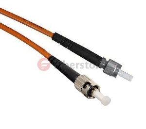
OM2 Multimode Fiber

The SMA-905 fiber optic patch cord, also known as FSMA connector, was one of the First fiber optic interconnect system that gained industry wide acceptance.SMA905 fiber patch cords make use of threaded connections and is still widely used for military, industrial, medical and Surgical applications and laser systems because of their low cost multimode coupling. It features simple termination and Assembly, and is TIA and IEC compliant. SMA 905 multimode connectors are available with stainless alloy or stainless steel ferrules.

1.2 A New Generation of Multimode Fiber Source

Traditional multimode fiber networks use light-emitting diode (LED) as light source . In low-speed network, which is an economically rational choice. However, LED is spontaneous emission light, the radiation -emitting laser is excited , the carrier lifetime is longer the former than the latter, and thus the LED modulation rate is limited , and not more than gigabit networks. Further, LED compared with a laser, the beam divergence angle, wide spectral width . After injection of multimode fiber , excite more high-order mode, the introduction of more wavelength components, so that the fiber bandwidth decreases . Fortunately 850nm vertical cavity surface emitting laser (VCSEL) not only has the advantage of these lasers, but aslo the price is basically the same with the LED. Other advantages of VCSEL are: low threshold current, may not be enlarged, driven directly by logic gates at 10Gb / s rate, get a few milliwatts of output power; emission wavelength of 850nm which does not apply to the standard single-mode fiber just for multimode fiber . At this wavelength, an inexpensive silicon detectors can be used and have a good frequency response; VCSEL another remarkable advantage is that the manufacturing process can be easily controlled distribution of the emitted light power , which is very advantageous for improving the bandwidth of MMF. It is because of these advantages, the new generation of multimode fiber standard will use 850nm VCSEL light source .

1.3 The Bandwidth Distance of Multimode Fiber Patch Cable

By comparing the above- described laser and LED , the use of multimode fiber laser light source, the transmission bandwidth should be greatly improved. However, experimental results show that simply make the bandwidth of a laser instead of LED light source, system is not only reduced but increased. IEEE Expert Group found through research, the bandwidth of multimode fiber and the optical fiber or the injection molding state of a power distribution. The preform fabrication process, the refractive index of the fiber axis prone to depression. Done before light source LED, is overfilled launch (OFL-Over Filled Launch), all of the fiber mode ( hundreds ) are excited to bring their own part of each module power. The refractive index of the fiber center delay characteristic distortion affects only a small number of models, the relatively limited impact on the modal bandwidth of the fiber. The measured multimode fiber bandwidth for the use of LED light source system is correct. However, when a laser light source, a laser beam spot is only a few microns, the divergence angle is smaller than the LED, so that only a small number of modes excited in the center of the fiber transmission, each mode carries a large part of the power, the refractive index of the fiber center distortion affect a small number of patterns of delay characteristics, so that decreased multimode fiber bandwidth. So it can not be measured with a laser light source for multimode fiber OFL bandwidth of conventional methods.

Today a new generation of multi-mode fiber main measurement bandwidth limit die by injection method (RML-Restricted Mode Launch). In this way the measured bandwidth is called ” laser -bandwidth ” or ” modal bandwidth limit “, previously done with the LED light source measured bandwidth is called “OFL bandwidth is .” Both represent the bandwidth of multimode fiber laser and LED light source with a time of injection. August 5, 2009, TIA Standards Committee released a new generation of bandwidth distance product standard multimode fiber , 850nm laser distance -bandwidth product of 470MHz.km, 850nm OFL bandwidth of distance product of 350MHz.km, 1300nm OFL bandwidth of distance plot to 500MHz.km. Incidentally, the bandwidth from the product of the above-described generation of the multi-mode fiber is only 3dB corresponding baseband bandwidth of multimode fiber, multimode fiber does not take more than a high-frequency band -pass region is also used when the transmission signal . Today, by orthogonal frequency division multiplexing (OFDM) technology , can make good use of multimode optical fiber through a high frequency band region , under conditions of use of the same fiber optic patch cable type, transmission using high frequency band signal through region greatly improved multi-mode fiber transmission capacity.

1.4 Source Injection Method

In actual use, the multimode fiber coupled laser and the following methods:

Bias injection: In order to avoid the deterioration of these lasers is injected directly into the bandwidth MMF appears, use the mode regulator
Connection (MCP Mode Conditioning Patch Cable), the laser output is coupled into a multimode fiber. Connection-mode regulator is a short Single Mode Fiber Cable, one end of which is coupled with the laser and the other end coupled to a multimode optical fiber. SMF output spot detouring from the multimode fiber axis at a distance, allowing the deviation from the range is 17 ~ 24μm, the aim is to avoid the center of the refractive index depression, but do not deviate too far, only one group is selectively lower-order mode excitation .

Centre injection: ideal for the refractive index profile, there is no central depression MMF can be used instead of the center of the injection molding
Regulator connection. The advantage of this is that the bandwidth of the laser can effectively improve the MMF to reduce the complexity of the network system and reduce system cost, a current-mode regulator 80 to the connection of approximately U.S. $ 100. Corning launched InfiniCor CL 1000 (62.5μm core diameter) and InfiniCor CL 2000 (50μm core diameter) is Gigabit Ethernet 1300nm wavelength laser directly into the mode without adjusting the first multi-connection mode fiber.

Simplex And Duplex Fiber Optic Cables

Share

It is important to understand the different varieties of core characteristics that are available within the fiber optic cabling itself, as each of these different characteristics will have different effects on your ability to transmit information reliably. Have a look at the most common fiber optics cores used in the industry nowadays.

Simplex optical fiber Cable

Simplex means this cable is with only one thread of fiber optic glass inside the single core. And simplex cables are with one single outer jacket. Simplex fiber optic cable is used in applications that only require one-way data transfer. For instance, an interstate trucking scale that sends the weight of the truck to a monitoring station or an oil line monitor that sends data about oil flow to a central location. There are singlemode and simplex multimode fiber optic cable available. Single-mode simplex fiber optic cable is a great option for anyone setting up a cable network that will require data to travel in one direction over long distances. Since this type of cable only carries one ray of light at a time, it’s better for long-distance transmissions. Single-mode fiber itself has a high-carrying capacity, is very reliable, and has lower power consumption than other options.

Analog to digital data readouts, interstate highway sensor relays, and automated speed and boundary sensors (for sports applications) are all great uses of Simplex fiber optic cable. This form of fiber cable can be cheaper than Duplex cables, because less material is involved. Simplex cable is compatible with any HDMI extender.

Duplex Fiber Optic Cables

Duplex fiber cable can be regarded as two simplex cables, either single mode or multimode, having their jackets conjoined by a strip of jacket material, usually in a zipcord (side-by-side) style. Use duplex multimode or singlemode fiber optic cable for applications that require simultaneous, bi-directional data transfer(One fiber transmits data one direction; the other fiber transmits data in the opposite direction). Duplex fiber is available in singlemode and multimode.

Duplex Fiber Cable and Singlemode duplex cable alike are used for two-way data transfers. Larger workstations, switches, servers, and major networking hardware tends to require duplex fiber optic cable. Duplex cables can be more expensive than Simplex cables, and are compatible with any HDMI extender.

Simplex and duplex are with various cable structure types; they are different from single mode and multi mode which are related to fiber optic glass types.

Multi Fiber Cables

Both multi fiber cables and simplex cables are with a single outer jacket, but simplex only has one thread fiber glass inside the core, while multi fiber has many threads of fiber optic glass inside the core. For example, an 8-core multi fiber cable. There are ribbon type and bundle type multi fiber cables.

Single-mode fiber cables and multi-mode fiber cables are similar in many ways, with the main difference being that the glass center of single-mode cables is significantly smaller, at about 10 microns in diameter. The smaller size is what allows these cables to transmit data up to 40 miles with a bandwidth of 1Gbs.

Only need a simplex fiber cable if data will be traveling in one direction, such as with a security camera or truck weigh station. And if your data will be traveling a long distance – for instance between buildings or from one station to another – then you’re better off with a single-mode fiber cable.

Fiber Optics And Cleaning Of Fiber Optic Connectors

Share

Fiber optics can be a revolutionary technology which has transformed the strategies of communication, making data considerably faster. We have which utilizes glass (or plastic) threads (fibers) to send out data. They carry numerous additional benefits as compared with metal wires with regards to data transfer useage. The fiber optic cable is made up of bundle of glass threads, which can do transmitting messages modulated onto light waves. The thin size optical cables makes them easy to set up, greater bandwidths allow greater data and less vunerable to any interference in the signals.

Advantages of fiber optics include:

  •  Faster connection speeds
  •  More bandwidth for phone lines, data transfer, videos, and television
  • Stronger signal over longer distances
  • Clearer phone conversations and video reception

Although benefits are plenty, yet a very important factor that holds importance is cleaning of fiber optic cables. Cleaning is to maintain normal running of the fiber optic method. In optical devices used process, for instance, optical fiber joint activities in various degrees may contamination by dust, dirt, the optical link loss increase, at this point the particular phenomenon seen as optical receiver optical power reduction, optical receiver output level is decreased obviously. In cases like this, the fiber connectors has to be properly clean maintenance. Light always travels in the straight path as well as a slight hindrance in its path can bring about data loss. So, to ensure that there is no data loss in fiber optic communication, it is necessary to clean fiber optics.

Not simply is the cleaning of fiber optics crucial, but the connectors which are utilized to connect the fiber optics need to be maintained and cleaned regularly. Cleaning of fiber optic connectors requires that you have a very little technical knowledge.

The first task in connector cleaning may be the cleaning of Ferrule, a cylindrical element of the connector which is generally comprised of stainless steel. The dwelling of an ferrule contains small holes in which the fiber cables are positioned. The fibers are engraved to suit with all the end face from the ferrule. With the aid of a mating sleeve, the 2 ferrules are contacted with each other within their end faces and additional transmission of sunshine signals comes about. Any blockage or damage in the form of dust or stain can distort the info connection and result in signal loss. So, to make certain that your communication channels are operating smoothly with no interruption inside the data flow you’ll want to perform the cleaning of fiber optical connections and cables with a timely basis.

There are various fiber optic tool kits you can purchase that can be used for cleaning of fiber optic cables installed at your home and also office. The very fact, that cleaning has to be done on a regular basis makes the cleaning kits more important for domestic use. By using these kits, you can save yourself in the need for calling professional cleaning providers when you look to clean your optical connections. FiberStore provide other fiber optic tool,for example Crimping tool,wire cutter etc. You’ll find your optical tools within our store.

Insert Loss And Return Loss For Fiber Connectors

Share

Optical fiber connector is connected to various devices communication systems are essential components, is currently the largest use of optical devices. Since the local optical fiber communication network gradually, metro and access network users increased demand, global fiber optic connector market in recent years, the total demand continues to expand, the annual growth rate over the next decade is expected to be around 20%.

Although there are more than 70 kinds of Fiber Connectors, and new varieties are still emerging. Typically, the measure of product quality fiber optic connector optical characteristics of the main indicators Insert loss and Return loss. In addition, the impact of product quality and reliability ferrule endface geometry and other physical characteristics of the system indicators are increasingly being valued by manufacturers or end customers. The following from the fiber optic connector works starting on the connector insertion and return loss as a brief introduction:

Fiber optic connectors can not be used, it must be the same with other types of connectors with each other, in order to form a light path connections. Insertion loss is the connector connecting the system with an optical power attenuation (i.e., the output power to the optical connector relative to the input power reduction amount). Insertion loss mainly by optical phase between successive two lateral deviation caused. For example, two optical fibers in alignment, laterally offset is zero, then the result of the minimum insertion loss. However, in the actual docking connector, this is unlikely to be achieved, since the core and the fiber cladding misalignment of the fiber cladding and the pin bore and the pin bore misalignment of the outer diameter of the concentric error, etc., will cause lateral deviation between the fibers.

Meanwhile, the fiber optic connector end face quality vertical clearances and insertion loss is caused by one of the factors commonly used in recent years, UPC plug contact way, you can solve the problem of vertical clearance. In this way, pins and fiber end is spherically polished, so that the two pins relative access under the action of external forces engaged with the engaging morph fiber and flattened, forming an optical fiber butt sufficient to reduce fiber connector vertical clearance.

Return loss is a measure of the back end connector to the size of the parameters of reflected light. The essence of the echo that is reflected light, according to Fresnel reflection principle, the light during the transmission encounter two different refractive index interface Fresnel reflection occurs, causing the optical path of the signal is superimposed or interfere. In high data rate systems of single-mode fiber, in particular cable television system (CATV), reflections of the transmitted signal is generated a time lag, so that the signal time delay to reach the client, cause image ghosting and decreased sharpness.

UPC connector connector contact manner, by reducing the gap between the connection end faces, in addition to reducing the insertion loss, but also reduces the connection end of the reflection and improve the return loss; while for other users of the CATV system, APC type contact method was a better choice: Because APC ceramic ferrule type connector end of its spherical axis normal to the fiber at an angle (usually 8 °), so that the light reflected from the end face escape without returning core, thus greatly improving the return loss of the connector.

Other info: Before installing any fiber optic system, you must first consider the approach to low-loss optical fiber or cable to connect to each other in order to achieve the optical link connection. Fiber link connection, can be divided into permanent and activities of two kinds. Permanent connection, they use a fiber splicing method(related:fiber splicer), bonding method or fixed connector to achieve; activity of continuation, the general activities of the connector to achieve.Want to know more fiber connectors info ,pls continue to focus on my blog.

Several Common Kinds of Fiber Optic Connectors

Share

Unlike Copper network cables, who have a standardized connector setup, fiber optic cables can employ many connector schemes to help make connections with patch panels, switch boxes, and the various fiber optic network implements that comprise a knowledge system.

Each of the different types of fiber optic connectors offers its advantages and disadvantages, and has its very own specific applications to which it’s best suited. Here’s a listing of one of the most common types of fiber optic connectors, their common uses, along with the advantages they can give your fiber optic network.

SC

Though there tend to be more types of fiber optic connector available on the market than can be adequately discussed here, the number of fiber optic connectors you’e planning to encounter inside a professional setting are relatively few. SC fiber optic connectors are probably the most common kinds of connector used for commercial purposes and realizing them will likely be needed for anyone using a fiber optic network.

The one outstanding good thing about SC fiber optic connectors is the snap-in design. This design lets them connect easily with other network implements. SC connectors have 2.5mm ferules and are well known for their reliable performance. Though they may be typically simplex (unidirectional) in nature, SC connectors with duplex (bidirectional) formatting can be purchased too.

SC connectors have widespread use within recent times, as a result of a welcome lowering of price. Ahead of this reduction, SC connectors were often subbed out for that less costly, though still technically impressive, ST connector.

ST

ST fiber optic connectors use a 2.5mm ceramic ferrule, including the SC fiber optic connector. However, whereas SC connectors mate using a snap-in mechanism, ST connectors work with a spring-loaded cinch to couple to network implements.

It is possible to typically find ST connector in older, large-scale multimode networks, such as those seen on business or academic campuses. The phrase multimode describes fiber optic cables which allow multiple propagation paths along which data can pass. ST connectors happen to be largely superseded about the consumer market by more modern connector schemes, nevertheless they can continue to deliver a satisfying performance for any large-scale network.

FC

Unlike the SC and ST connectors we merely discussed, FC fiber optic connectors are usually used with singlemode fiber optic cables offering one propagation path along which information can travel. Singlemode fiber optic cables are generally useful for cabling over longer distances than multimode fiber optic cables. Many datacom and telecom systems employ FC connectors for this specific purpose.

The FC fiber optic connector features a 2.5mm ceramic ferrule and effects its connections through a screw-type fasten.

LC

Which has a size only half those of the SC, ST, and FC fiber optic connectors, the LC fiber optic connector is a great option for cable terminations that must be effected quickly with little hassle. LC connectors possess a 1.25mm ceramic ferrule and provide reliable performance for singlemode fiber optic cables. Many pieces of communications technology that need high-density connections including SFP and XFP transceiver will employ LC fiber optic connectors.

MT-RJ

The MTRJ connector can be a somewhat different beast as opposed to connectors we discussed to date. The initials MTRJ stand for Mechanical Transfer Registered Jack. MTRJ connectors are designed to mimic the scale and type of the RJ-45 connectors typically that comes with the ends of Cat5, Cat5e, and Cat6 network cables.

With a single, polymer ferrule, MTRJ connectors are capable of making connections only with duplex, multimode fiber optic cables. Many adapters that will transfer data between a fiber optic network and a conventional, UTP data network, will employ MTRJ connectors because of their relative convenience.

Toslink

Much like the MTRJ connector, the Toslink connector serves a specialized purpose. Toslink connectors are some of the few fiber optic connectors intended almost only for the individual market. Sometimes referred to as optical audio connectors, Toslink connectors are prepared for carrying digital audio signals between audio sources and loudspeakers, via fiber optic cables.

The initial aim of the Toslink connector ended up being form connections between CD players and residential stereo systems. Today, Toslink connectors can be used connecting DVD players, Blu-Ray players, and computer game consoles to digital home theatre systems.

At fs.com obscurity is our obsession. Our passion to deliver large choice of Connectors. Find Fiber Connectors including SC, ST, FC, LC, MT-RJ, Toslink, plus much more!