Monthly Archives: January 2016

40G Network Connectivity Solutions

Share

High speed and wide bandwidth demands drive data centers to consolidate into more complex systems. The speed of data center now is increasing to 40G and eventually to 100G. How to achieve 40G connectivity? In fact, we need some new optical technologies and cabling infrastructure. In this post, I will introduce some commonly used qsfp and qsfp cable for 40G connectivity.

40G QSFP Modules
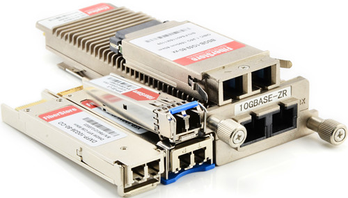
As we know, fiber optic transceiver is an electronic device that receives an electrical signal, converts it into a light signal, and launches the signal into a fiber. It also receives the light signal, from another transceiver, and converts it into an electrical signal. It is the key component in fiber optic transmission. The basic interface of 40G pluggable optical modules are 40GBASE-LR4 and 40GBASE-SR4 in QSFP+ form factor.

40G QSFP+

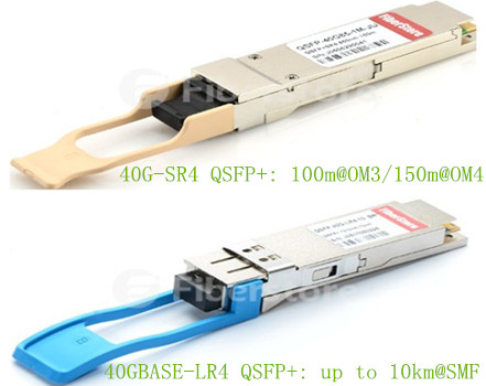
1. 40GBASE-SR4 QSFP+
40GBASE-SR4 transceivers are used in data centers to interconnect two Ethernet switches with 8 fiber parallel multimode fiber OM3/OM4 cables. It can support the transmission distance up to 100 m with OM3 fiber and 150 m with OM4 fiber. The optical interface of 40GBASE-SR4 is MPO/MTP. This module can be used for native 40G optical links or in a 4x10G mode with parallel to duplex fiber breakout cables for connectivity to four 10GBASE-SR interfaces.

2. 40GBASE-LR4 QSFP+
40GBASE-LR4 QSFP+ transceiver support with a link length up to 10 kilometers over 1310 nm single-mode fiber with duplex LC connectors. The 40 Gigabit Ethernet signal is carried over four wavelengths. Multiplexing and demultiplexing of the four wavelengths are managed within the device. It is most commonly deployed between data-center or IXP sites with single-mode fiber.

QSFP+ Cables
QSFP+ cable is designed to meet emerging data center and high performance computing application needs for a short distance and high density cabling interconnect system capable of delivering an aggregate data bandwidth of 40Gb/s. QSFP+ cables are suitable for very short distances and offer a highly cost-effective way to establish a 40G link between two switches within racks and across adjacent racks. These high speed cables provide a highly cost-effective way to upgrade from 10G to 40G or 40G to 40G interconnect connection.

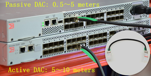
1. Passive and Active Direct Attach Copper Cables
The 40g passive or active direct attach copper cables (DAC) are designed with twinax copper cable and terminated with QSFP+ connectors. The main difference between passive DAC and active DAC is that the passive one is without the active component. Therefore, active QSFP+ DAC can achieve a longer transmission distances than passive QSFP+ cable.

0.5m(1.6ft)-passive-40gbase-qsfp+-dac

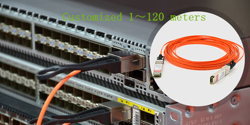
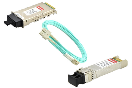
2. Active Optical Cable (AOC cable) Assemblies
Active optical cable, namely AOC brings a more flexible cabling than direct attach copper cables with the advantages of lighter weigth, longer transmission distance and higher performance for anti-EMI. Now, 40G AOC cable are popular with users.

10m(32.8ft)-40gbase-qsfp+-to-qsfp+-aoc

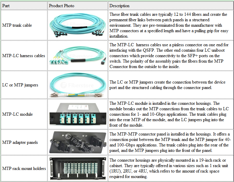
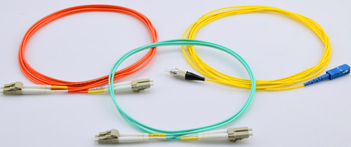
MPO/MTP Cable Series
Since 40GBASE-SR4 and 40GBASE-CSR4 both use MPO/MTP connector. Therefore, in addition to fiber optic transceivers and direct attach cables, MTP cabling series usually needed to achieve 40G connectivity. This series include MTP trunk cables, MTP-LC harness/breakout cables, LC or MTP patch cables, MTP-LC cassette modules, MTP adapter panels and MTP rack mount holders.

MPOMTP Cabling Series

Fiberstore offers a comprehensive solution for 40G network connectivity. What’s more, products such as 40GBASE-LR4 and 40GBASE-SR4 modules are in stock and can shipped in 12hrs. For more information, please visit www.fs.com.

Related article: Do You Know about Active Optical Cable (AOC Cable)

Which SFP Fiber Cable Should I Choose for My Optical Transceiver?

Share

SFP fiber cable and fiber optic transceiver have become more and more important in fiber optic data transmission, especially in data transmission between the switches and equipment. But with so many different kinds of SFP fiber cables available in the market, which one is suitable for may optical transceiers? This article may on this issue to provide some solutions. Before starting this topic, it is necessary for us to review the basic knowledge of the fiber optic transceiver and fiber optic cable.

Fiber Optic Transceiver Overview
Fiber Optic Transceiver is a self-contained component that can both transmit and receive. Usually, it is inserted in devices such as switches, routers or network interface cards which provide one or more transceiver module slot. There are many optical transceivers types, such as SFP+ transceiver, X2 transceiver, XENPAK transceiver, XFP transceiver, SFP (Mini GBIC) transceiver, GBIC transceiver and so on.

Fiber Optic Transceiver

Fiber Optic Patch Cable Overview
Fiber optic patch cable, also known as fiber jumper or fiber optic patch cord. It is composed of a fiber optic cable terminated with different connectors on the ends. Fiber optic patch cables are used in two major application areas: computer work station to outlet and patch panels or optical cross connect distribution center. According to fiber cable mode, cable structure or connector types etc., fiber patch cable can be divided into different types.

SFP Fiber Cable

1.Single-mode and Multimode SFP fiber Cable
According cable mode, patch cables can be divided into single-mode and multimode fiber patch cable. The word mode means the transmitting mode of the fiber optic light in the fiber optic cable core. Single-mode patch cables are with 9/125 fiber glass and are yellow jacket color, while multimode patch cables are with OM1 62.5/125 or OM2 50/125 fiber glass and are orange color. In addition, there is 10G OM3 and OM4 multimode patch cables which cable jacket are usually aqua.

2.Simplex and Duplex SFP fiber Cable
Simplex fiber patch cable is consist of single fiber core, while duplex fiber patch cable is consist of two fiber cores and can be either singlemode or multimode. Additionally, there is also ribbon fan-out cable assembly (ie. one end is ribbon fiber with multi fibers and one ribbon fiber connector such as MTP connector (12 fibers), the other end is multi simplex fiber cables with connectors such as ST, SC, LC, etc.).

3.LC, SC, ST, FC, MT-RJ, E2000, MU and MPO/MTP Patch Cable
Fiber optic patch cable can be also classified by the types of fiber optic connector. For example, LC fiber optic patch cable is named as it is with LC connector. Similarly, there are SC, ST, FC, MT-RJ, E2000, MU and MPO/MTP fiber optic patch cables. What’s more, there are PC, UPC, APC type fiber patch cords, which are differentiated from the polish of fiber connectors.

Which SFP fiber Cable Should I Choose for My Fiber Optic Transceivers?
Now, I will take the Cisco fiber optic transceiver as an example to discuss this topic. For example, we need to choose a right patch cable to connect Cisco fiber optic transceiver SFP-10G-SR and X2-10GB-SR. Which patch cable to use? According to “Cisco 10-Gigabit Ethernet Transceiver Modules Compatibility Matrix”, we may know that SFP-10G-SR is the 10GBASE-SR SFP+ transceiver module for MMF, 850-nm wavelength, LC duplex connector. And X2-10GB-SR is the 10GBASE-SR X2 transceiver module for MMF, 850-nm wavelength, SC duplex connector. Obviously, this two knids of optica trancseivers are both for MMF, so we should choose a multimode patch cable. Besides, we know X2-10GB-SR is designed for SC duplex connector and the SFP-10G-SR is designed for duplex LC connector, so we should use a patch cable with SC-LC duplex connector.

Which Patch Cable Should I Choose for My Fiber Optic Transceivers

The Most Common Used SFP fiber Cable Selection
In the way mentioned above, you could choose right fiber patch cable for your other transceiver modules. Keep in mind that if your transceiver modules are not Cisco’s, you need to ask your brand supplier to get the corresponding compatibility matrix. In fact, in terms of a same kind of optical transceiver, different supplier may provide the transceiver with different specifications. Here I may list the most common used patch cables selection. Hope to give you smoe reference.

Fiber optic patch cable Applicable fiber optic transceiver connection
LC-LC Simplex 9/125 Single-mode Fiber Patch Cable 1.25Gbps 1310nmTX/1490nmRX BiDi SFP

10GBASE 1270nmTX/1330nmRX BiDi SFP+

LC-LC Duplex 9/125 Single-mode Fiber Patch Cable 1000Base-LX/LH 1310nm 10km LC SMF SFP
LC-SC Duplex 9/125 Single-mode Fiber Patch Cable Cisco X2-10GB-LR , Cisco XENPAK-10GB-LR and Cisco SFP-10G-LR
SC-LC Duplex 10G OM4 50/125 Multimode Fiber Patch Cable Cisco XENPAK-10GB-SR , Cisco X2-10GB-SR and Cisco SFP-10G-SR
LC-LC Duplex OM1 62.5/125 Multimode Fiber Patch Cable 100Base-FX 2km 1310nm MMF LC SFP
LC-LC Duplex OM2 50/125 Multimode Fiber Patch Cable 1000Base-SX 850nm 550m LC MMF SFP
LC-LC Duplex 10G OM3 50/125 Multimode Fiber Patch Cable 10GBASE-SR 850nm 300m Multi-Mode SFP+
LC-LC Duplex 10G OM4 50/125 Multimode Fiber Patch Cable Cisco SFP-10G-SR Compatible 10GBASE-SR SFP+

Related Article: Differences Between SFP, BiDi SFP and Compact SFP

Related Article: Cisco SFP-10G-SR: All You Need to Know

40GBASE-LR4 QSFP+ Transceiver Links: CWDM and PSM

Share

As we all know, 40GBASE-SR4 QSFP+ transceivers usually use a parallel multimode fiber (MMF) link to achieve 40G. It offers 4 independent transmit and receive channels, each capable of 10G operation for an aggregate data rate of 40G over 100 meters of OM3 MMF or 150 meters of OM4 MMF. However, for 40GBASE-LR4 QSFP+ transceivers, there are two kinds of links. One is coarse wavelength division multiplexing (CWDM) and the other is parallel single-mode fiber (PSM). What’s the difference between them? In this article, I will show their working principles to you respectively.

40GBASE-LR4 CWDM QSFP+ Transceiver
QSFP-40G-LR4The 40GBASE-LR4 CWDM QSFP+ transceiver, such as QSFP-40GE-LR4, is compliant to 40GBASE-LR4 of the IEEE P802.3ba standard. It contains a duplex LC connector for the optical interface. The maximum transmission distance of this transceiver is 10km. To minimize the optical dispersion in the long-haul system, single-mode fiber (SMF) has to be used. This transceiver converts 4 inputs channels of 10G electrical data to 4 CWDM optical signals by a driven 4-wavelength distributed feedback (DFB) laser array, and then multiplexes them into a single channel for 40G optical transmission, propagating out of the transmitter module from the SMF. Reversely, the receiver module accepts the 40G CWDM optical signals input, and demultiplexes it into 4 individual 10G channels with different wavelengths. The central wavelengths of the 4 CWDM channels are 1271, 1291, 1311 and 1331 nm as members of the CWDM wavelength grid defined in ITU-T G694.2. Each wavelength channel is collected by a discrete photo diode and output as electric data after being amplified by a transimpedance amplifier (TIA).

40G CWDM QSFP+

40GBASE-LR4 PSM QSFP+ Transceiver
40G-LR4 QSFPUnlike CWDM QSFP+ transceiver which uses a LC connector, PSM QSFP+ is a parallel single-mode optical transceiver with an MTP/MPO fiber ribbon connector. It also offers 4 independent transmit and receive channels, each capable of 10G operation for an aggregate data rate of 40G on 10km of single-mode fiber. Proper alignment is ensured by the guide pins inside the receptacle. The cable usually cannot be twisted for proper channel to channel alignment. In terms of a PSM QSFP+, the transmitter module accepts electrical input signals compatible with common mode logic (CML) levels. All input data signals are differential and internally terminated. The receiver module converts parallel optical input signals via a photo detector array into parallel electrical output signals. The receiver module outputs electrical signals are also voltage compatible with CML levels. All data signals are differential and support a data rates up to 10.3G per channel.

40G PSM QSFP+

What’s the Difference?
From an optical transceiver module structure viewpoint, PSM seems more cost effective because it uses a single uncooled CW laser which splits its output power into four integrated silicon modulators. Besides, its array-fiber coupling to an MTP connector is relatively simple. However, from an infrastructure viewpoint, PSM would be more expensive when the link distance is long, mainly due to the fact that PSM uses 8 optical single-mode fibers while CWDM uses only 2 optical single-mode fibers. A summary table comparing the key differences between CWDM and PSM is shown below:

Name CWDM PSM
Optical TX 4 uncooled 1300nm CWDM directly-modulated laserswavelength spacing 20 nm 4 integrated silicon photonic modulators and one CW laseruncooled 1300nm DFB laser
4-wavelength CWDM multiplexer and demultiplexer Needed No need
Connector Duplex LC connector MTP/MPO fiber ribbon connector
Cable Via 2 optical single-mode fibers Via 8 optical single-mode fibers

In addition, the caveat is that the entire optical fiber infrastructure within a data center, including patch panels, has to be changed to accommodate MTP connectors and ribbon cables, which are more expensive than conventional LC connectors and regular SMF cables. What’s more, cleaning MTP connectors is not a straightforward task. Therefore, CWDM is a more profitable and popular 40G QSFP link.

Conclusion
For 40GBASE-LR4 QSFP+ transceivers, either CWDM link or PSM link, the maximum transmission distance is both 10km. 40GBASE-LR4 CWDM QSFP+ transceivers use a duplex LC connector via 2 optical single-mode fibers to achieve 40G. However, 40GBASE-LR4 PSM QSFP+ transceivers use an MTP/MPO fiber ribbon connector via 8 optical single-mode fibers to reach 40G. Therefore, CWDM QSFP+ enables data center operators to upgrade to 40G connectivity without making any changes to the previous 10G fiber cable plant, which is more cost-effective and widely used by people. Fiberstore provides wide brand compatible 40G CWDM QSFP+ transceivers, such as Juniper compatible JNP-QSFP-40G-LR4 and HP compatible JG661A. In Fiberstore, each fiber optic transceiver has been tested to ensure its compatibility and interoperability. Please rest assured to buy. For more information or quotation, please contact us via sales@fs.com.

Related Article: 40G Transceiver Module: QSFP+ Module And CFP Module

How to Test a Fiber Optic Transceiver?

Share

Transceiver testWhen optical transceivers was first deployed, verifying the performance of it was straightforward. The entire network was installed and owned by a single company, and if the system worked, extensive testing of the subcomponents was unnecessary. Today, however, most optical networks use components that may come from a variety of suppliers. Therefore, to test the compatibility and interoperability of each fiber optic transceiver becomes particularly important. How to test a fiber optic transceiver? This article may give you the answer.

As we all know, basically, a fiber optical transceiver consists of a transmitter and a receiver. When a transmitter through a fiber to connect with a receiver but the system doesn’t achieve your desired bit-error-ratio (BER), is the transmitter at fault? Or, is it the receiver? Perhaps both are faulty. A low-quality transmitter can compensate for by a low-quality receiver (and vice versa). Thus, specifications should guarantee that any receiver will interoperate with a worst-case transmitter, and any transmitter will provide a signal with sufficient quality such that it will interoperate with a worst-case receiver.

Precisely defining worst case is often a complicated task. If a receiver needs a minimum level of power to achieve the system BER target, then that level will dictate the minimum allowed output power of the transmitter. If the receiver can only tolerate a certain level of jitter, this will be used to define the maximum acceptable jitter from the transmitter. In general, there are four basic steps in testing an optical transceiver, as shown in the following picture, which mainly includes the transmitter testing and receiver testing.

Fiber Optic Transceiver test

Transmitter Testing
Transmitter parameters may include wavelength and shape of the output waveform while the receiver may specify tolerance to jitter and bandwidth. There are two steps to test a transmitter:
Transmitter Testing1. The input signal used to test the transmitter must be good enough. Measurements of jitter and an eye mask test must be performed to confirm the quality using electrical measurements. An eye mask test is the common method to view the transmitter waveform and provides a wealth of information about overall transmitter performance.

Transmitter Testing2. The optical output of the transmitter must be tested using several optical quality metrics such as a mask test, OMA (optical modulation amplitude), and Extinction Ratio.

Receiver Testing
To test a receiver, there are also two steps:
Receiver Testing3. Unlike testing the transmitter, where one must ensure that the input signal is of good enough quality, testing the receiver involves sending in a signal that is of poor enough quality. To do this, a stressed eye representing the worst case signal shall be created. This is an optical signal, and must be calibrated using jitter and optical power measurements.

4. Finally, testing the electrical output of the receiver must be performed. Three basic categories of tests must be performed:

  • A mask test, which ensures a large enough eye opening. The mask test is usually accompanied by a BER (bit error ratio) depth.Receiver Testing
  • Jitter budget test, which tests for the amount of certain types of jitter.
  • Jitter tracking and tolerance, which tests the ability of the internal clock recovery circuit to track jitter within its loop bandwidth.

In summary, testing a fiber optic transceiver is a complicated job, but it is an indispensable step to ensure its performance. Basic eye-mask test is an effective way to test a transmitter and is still widely used today. To test a receiver seems more complex and requires more testing methods. Fiberstore provides all kinds of transceivers, which can be compatible with many brands, such as Cisco, HP, IBM, Arista, Brocade, DELL, Juniper etc. In Fiberstore, each fiber optic transceiver has been tested to ensure our customers to receive the optics with superior quality. For more information about the transceivers or compatible performance test, please visit www.fs.com or contact us over sales@fs.com.

Related Article: What Is An Optical Module?

Related Article: Optical Module Maintenance Methods and Installation Tips