Daily Archives: May 25, 2015

40 Gigabit Ethernet Options Guideline

Share

When the IEEE introduced the 802.3ba Ethernet standard, this was in response to the increasing bandwidth demands facing data centers, paving the way for the introduction of 40Gb/s and 100Gb/s Ethernet operations. Believe it or not, the 40 Gigabit Ethernet era is already upon us. This text put together a brief overview of the current 40 Gigabit Ethernet optics types and form factors to aid in planning for future high-performance Ethernet needs.

40 Gigabit Ethernet Standards
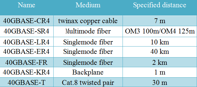
The IEEE 802.3ba introduced the 40 Gigabit and 100 Gigabit Ethernet standards in 2010. 802.3ba is the designation given to the higher speed Ethernet task force which completed its work to modify the 802.3 standard to support speeds higher than 10 Gbit/s. This was the first time two different Ethernet speeds were specified in a single standard. The table below gives detailed specifications for 40 Gigabit Ethernet standards.

40 Gigabit Ethernet qsfp

40 Gigabit Ethernet QSFPTransceiver Options
As with any new generation of technology, one design goal was to leverage as much existing technology as possible. By minimizing the number of new interfaces, the interfaces become less expensive and take advantage of volume production and simplicity. To meet this design goal, there are three media modules will be used in the first generation of 40 Gigabit Ethernet: QSFP, CXP and CFP.

  • QSFP
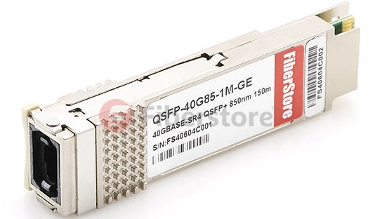
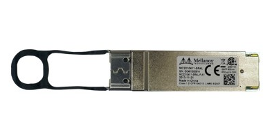
    The Quad Small-Form-Factor Pluggable (QSFP) is similar in size to the CXP and provides four transmit and four receive lanes to support 40 Gigabit Ethernet applications for multimode fiber and copper today and may serve single-mode in the future. Another future role for the QSFP may be to serve 100 Gigabit Ethernet when lane rates increase to 25 Gbps.

QSFP

  • CXP
    The CXP transceiver features 12 transmit and 12 receive 10-Gbps lanes to support one 100 Gigabit Ethernet port, or up to three 40 Gigabit Ethernet ports. It can achieve rates up to 120 Gbps of pluggable data over 12 lanes in one assembly while enhanced-footprint connectors transmit signals over 10 lanes for up to 100 Gbps.

CXP

  • CFP
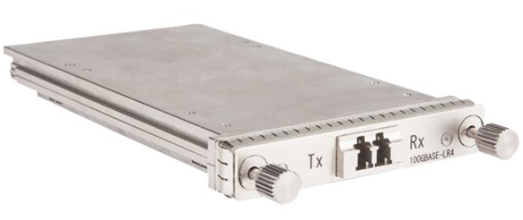
    The C Form-Factor Pluggable (CFP) is a new media module that was designed for longer-reach applications, with up to 24 watts of power dissipation. Its dense electrical connectors and integrated, riding heat sink enable a range of interfaces. This module is used for 40GBASE-SR4, 40GBASE-LR4.

CFP

40GbE Cabling Options

The most common 40GbE cable is the QSFP+ Cable. Such as QSFP direct attach copper cable (DAC) and QSFP active optical cable (AOC). Besides, the MPO/MTP cable is considered the best solution for 40GbE. Since MPO/MTP connectors have either 12 fibres or 24 fibres array, which can allow data transmission across multiple fibres simultaneously.

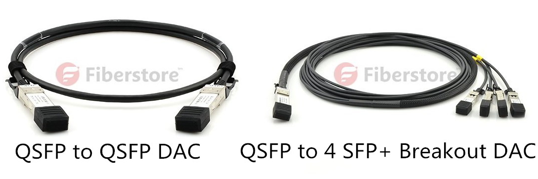
  • Direct Attach Copper Cable

Transmitting 40 GbE over short distances of parallel coaxial copper cabling (also referred to as twinax cabling) is accomplished using a special cabling assembly with four lanes of coaxial cabling (eight pairs). Four pairs each transmit 10 Gbps in one direction and four transmit 10 Gbps in the other direction for a total data rate of 40 Gbps. The two common DACs used in 40g Ethernet are QSFP to QSFP and QSFP to 4 SFP+ copper direct-attach cables.

40G DAC

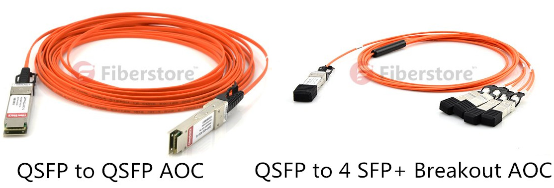
  • Active Optical Cable

In the market, there are two common 40g fiber cable: QSFP to 4 SFP+ breakout AOC and QSFP to QSFP AOC. The former is a 4×10 Gb/s parallel active optical cable which transmits four separate streams of 10 Gb/s data over ribbon cables in a point-to-multipoint configuration. The cable contains a QSFP+ module on one end and four separate SFP+ modules at the other ends. The latter is a 40 Gb/s parallel active optical cable which transmits error-free parallel 4×10 Gb/s data over multimode fiber (MMF) ribbon cables.

40G AOC

  • MPO/MTP Cable

Current multi-mode optics standards for 40GbE optics use multiple 10Gbps lasers, simultaneously transmitting across multiple fiber strands to achieve high data rates. Because of the multi-lane nature of these optics, 40GbE multi-mode optics use a different style of fiber cabling, known as MPO or MTP cabling. As with 10GbE optics over multi-mode fiber, an OM3 or OM4 grade MMF is needed to be able to cover longer distances. For 40g Ethernet, we can use 8 fibers MPO/MTP harness cables or 12 fibers MPO/MTP trunk cables. The former is to directly connect a QSFP port to other 4 SFP+ ports. The latter is to directly connect one QSFP port to another QSFP port.

MPO/MTP cable

Related articles:

40G Network Connectivity Solutions
MTP Fiber Cable Solutions
Three Types MTP Harness Cables Used in Today’s Data Center

Capacity Expansion and Flexibility—DWDM Network

Share

DWDM increases the bandwidth of an optical fiber by multiplexing several wavelengths onto it. Even though it costs more than CWDM, it is currently the most popular WDM technology because it offers the most capacity. This article provides an overview of DWDM networks and its current applications.

Introduction of DWDM Technology
Dense wavelength-division multiplexing (DWDM) revolutionized data transmission technology by increasing the capacity signal of embedded fiber. This increase means that the incoming optical signals are assigned to specific wavelengths within a designated frequency band, then multiplexed onto one fiber. By providing channel spacings of 50 GHz (0.4 nm), 100 GHz (0.8 nm) or 200 GHz (1.6 nm), several hundreds of wavelengths can be placed on a single fiber. DWDM takes advantage of the operating window of the Erbium Doped Fibre Amplifier (EDFA) to amplify the optical channels and extend the operating range of the system to over 1500 kilometers. The following picture shows the operation of a DWDM system.

Bi-Directional-DWDM-Operation

Components of DWDM System
Important components for DWDM systems are transmitters, receivers, optical amplifiers, transponders, DWDM multiplexers, and DWDM demultiplexer. These components, along with conforming to ITU channel standards, allow a DWDM system to interface with other equipment and to implement optical solutions throughout the network.

  • Optical transmitters/receivers

Transmitters are described as DWDM components since they provide the source signals which are then multiplexed. The characteristics of optical transmitters used in DWDM systems are highly important to system design. Multiple optical transmitters are used as the light sources in a DWDM system. Here we can ues a transceiver to replace transmitters and receivers, since it is the combiantion of them. Transceivers applied in DWDM network are often called the DWDM transceiver, of which the transmission distances can reach up to 120 km. The following picture shows the receivers and transmitters in DWDM systems.

Optical transmitters/receivers

  • Optical amplifiers

Optical amplifiers (OAs) boost the amplitude or add gain to optical signals passing on a fiber by directly stimulating the photons of the signal with extra energy. They are “in-fiber” devices. OAs amplify optical signals across a broad range of wavelengths. This is very important for DWDM system application. Erbium-doped fiber amplifiers (EDFAs) are the most commonly used type of in-fiber optical fibre. Following picture shows the operation of OA.

Optical amplifiers

  • Transponders

Transponders convert optical signals from one incoming wavelength to another outgoing wavelength suitable for DWDM applications. Transponders are optical-electricaloptical (O-E-O) wavelength converters. A transponder performs an O-E-O operation to convert wavelengths of light. Within the DWDM system a transponder converts the client optical signal back to an electrical signal (O-E) and then performs either 2R (reamplify, reshape) or 3R (reamplify, reshape, and retime) functions. The following picture shows the operation of bidirectional transponder.

Transponders

A transponder is located between a client device and a DWDM system. From left to right, the transponder receives an optical bit stream operating at one particular wavelength (1310 nm). The transponder converts the operating wavelength of the incoming bitstream to an ITU-compliant wavelength. It transmits its output into a DWDM system. On the receive side (right to left), the process is reversed. The transponder receives an ITU-compliant bit stream and converts the signals back to the wavelength used by the client device.

  • DWDM Multiplexers and Demultiplexers

Multiple wavelengths (all within the 1550 nm band) created by multiple transmitters and operating on different fibers are combined onto one fiber by way of an optical multiplexer. The output signal of an optical multiplexer is referred to as a composite signal. At the receiving end, a demultiplexer separates all of the individual wavelengths of the composite signal out to individual fibers. The individual fibers pass the demultiplexed wavelengths to as many optical receivers. Typically, mux and demux (transmit and receive) components are contained in a single enclosure. Optical mux/demux devices can be passive. Component signals are multiplexed and demultiplexed optically, not electronically, therefore no external power source is required. Following picture shows the operation of DWDM multiplexers and demultiplexers.

DWDM Multiplex and Demultiplex

Applications for DWDM
As occurs with many new technologies, the potential ways in which DWDM can be used are only beginning to be explored. Already, however, the technology has proven to be particularly well suited for several vital applications.

  • DWDM is ready made for long-distance telecommunications operators that use either point–to–point or ring topologies. The sudden availability of 16 new transmission channels where there used to be one dramatically improves an operator’s ability to expand capacity and simultaneously set aside backup bandwidth without installing new fiber.
  • This large amount of capacity is critical to the development of self-healing rings, which characterize today’s most sophisticated telecom networks. By deploying DWDM terminals, an operator can construct a 100% protected, 40 Gb/s ring, with 16 separate communication signals using only two fibers.
  • Operators that are building or expanding their networks will also find DWDM to be an economical way to incrementally increase capacity, rapidly provision new equipment for needed expansion, and future–proof their infrastructure against unforeseen bandwidth demands.