Connectors and other types of optical devices on the output of the transmitter may cause reflection, absorption, or scattering of the optical signal. These effects on the light beam may cause light energy to be reflected back at the source and interfere with source operation. To reduce the effects of the interference, an Optical Isolator is used. Many laser-based transmitters and Optical Amplifiers use an optical isolator because the components that make up the optical circuit are not perfect.
The optical isolator comprises elements that will permit only forward transmission of the light; it does not allow for any return beams in the fiber transmission routes or in the optical amplifiers. There are a variety of optical isolator types, such as Polarized (dependent and independent), Composite, and Magnetic.
Polarized Optical Isolator
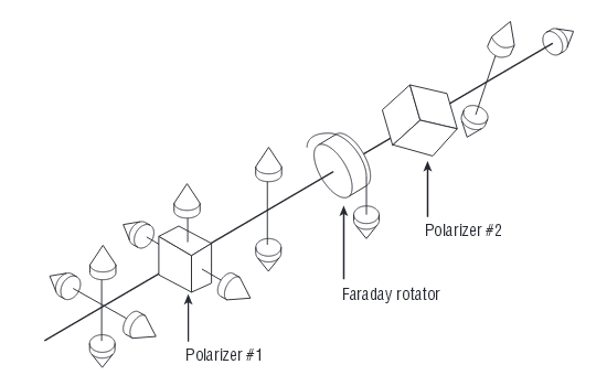
As mentioned, the Polarized Optical Isolator transmits light in one direction only. This is accomplished by using the polarization axis of the linearly polarized light. The incident light is transformed to linearly polarized light by traveling through the first polarizer. The light then goes through a Faraday rotator; this takes the linearly polarized light and rotates the polarization 45 degrees, then the light passes through the exit polarizer. The exit polarizer is oriented at the same 45 degrees relative to the first polarizer as the Faraday rotator is. With this technique, the light is passed through the second polarizer without any attenuation. This technique allows the light to propagate forward with no changes, but any light traveling backward is extinguished entirely.
The loss of backward-traveling light occurs because when the backward light passes through the second polarizer, it is shifted again by 45 degrees. The light then passes through the rotator and again is rotated by 45 degrees in the same direction as the initial tilt. So when the light reaches the first polarizer, it is polarized at 90 degrees. And when light is polarized by 90 degrees, it will be “shut out.” The figures below show the forward- and reverse-transmitted light in a dependent polarized optical isolator.
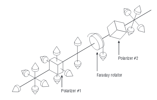
It should be noted that these figures depict the dependent type of polarized optical isolator. There is also an independent polarized optical isolator. The independent device allows all polarized light to pass through, not just the light polarized in a specific direction. The principle of operation is roughly the same as the dependent type, just slightly more complicated. Tips: The Independent Optical Isolators are frequently used in EDFA Optical Amplifiers.
Composite Optical Isolator
In fact, Composite Optical Isolator is a type of polarization independent isolator used in the EDFA optical amplifier. The EDFA optical amplifier is comprised of Erbium-Doped Fiber, Wavelength-Division Multiplexer, Pumping Diode Laser, Polarization Independent Isolator, and other passive components. Because the polarization independent isolator is composited with the others components into a single EDFA module, it is called a Composite Optical Isolator.
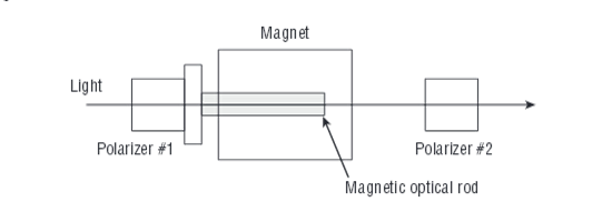
Magnetic Optical Isolator
Magnetic Optical Isolator is another name for polarized optical isolator. The magnetic portion of any isolator is of great importance. As mentioned, there is a Faraday rotator in the optical isolators. The Faraday rotator is a rod composed of a magnetic crystal having a Faraday effect and operated in a very strong magnetic field. The Faraday rotator ensures that the polarized light is in the correctly polarized plane, thus ensuring that there will be no power loss. Here is a figure that shows a basic magnetic optical isolator.
Optical isolators are used to ensure stabilization of laser transmitters and optical amplifiers as well as to maintain good transmission performance. Ultra speed and large capacity optical fiber trunk systems are expanding as a result of the development of optical amplifiers. In parallel, the demand for optical isolators is increasing. Demand is also expected to increase as LAN and other subscriber fiber optic networks expand. It is therefore imperative that optical isolators be further improved to achieve higher performance, smaller size, and lower price. Luckily, you can now find the best optical isolators solution in Fiberstore, a Manufacturer & Supplier of Fiber Optic Network Solutions focus on Professional Customization.
Related Article: Which Patch Cable Should I Choose for My Optical Transceiver?