Monthly Archives: December 2014

The LC Connector in Fiber Management and Transceivers

Share

The LC connector system, standardized as TIA/EIA FOCIS-10, was designed specifically to address the needs of increasing network interconnect density.

In the past, fiber management systems (for D4, ST, FC and Biconic),have required twice as many individual connectors as copper systems, hence, crowding racks and closets (Fig. 2) with additional patch bays, management hardware and line terminating electronics. SFF connectors have either a unitary body design (FJ and MT-RJ) or a provision for clipping simplex connectors together to form a single SFF end (LC).

The LC connector provides the potential for twice the interconnect density in closets and racks when compared to a SC connector. Although, there is a point at which additional density cannot be utilized because of the difficulty in fiber routing inordinately large cable counts. Also at issue in these higher density racks, is the problem of disturbing adjacent circuits in MACs. Most important in fiber management, is the decreased footprint of the LC on electronics (hubs, switches, etc.) for fiber transceivers.

SFF Connector, SFP Transceivers and the march towards 10Gb/s Enterprise Networking

Original SFF transceivers (GBICs) on equipment have now been overshadowed by the SFP (“pluggable”versions of the SFF) transceiver. Equipment vendors are starting to offer SFP on switches/NICs for Gb/s Ethernet. The optical receptacle on the SFP for Fibre Channel and Gb/s Ethernet is the LC connector. Most major transceiver vendors, including early proponents of “MT-RJ-only” transceivers, now sell SFPs with the LC interface only.

On 200 pin XenPAK transceivers, only SFF options are specified in the Multi Source Agreement (MSA). Vendors have offered XenPAK with both SC and LC pigtails, but the majority offers “LC only” XenPAK product lines. The LC is also used in competing transceivers such as XenPAK, X2 and XFP.

LC Market Acceptance

The LC is the market leader in SFF connectors. Press releases from the major vendors of LCs (Lucent) and MT-RJs (Tyco/AMP) in similar time frames (mid 01) indicate unit volumes of 20 million and 3 million respectively.

According to the Fiber Optic Connector/Mechanical Splice Global Market Report by Electronicast, the North American Market for private network use of SFF connectors is expanding quite rapidly. In this report, the multimode LC is estimated to grow at double the rate of that of the multimode MT-RJ (Table 1). The difference embedded in the Electronicast data is the creation of new installations (LC) versus the support of existing facilities (MT-RJ).

The multimode MT-RJ found early support in 100BASE-F applications. In spite of this, the LC is becoming the optoelectronics interconnect solution for 1-10Gb/s applications. The emerging 10Gb/s market has forced transceiver vendors to evolve toward pluggable designs with the LC as the primary choice of interconnect.

The LC connector patch cable have LC to LC, LC to MT-RJ, LC to SC, LC ST fiber patch cable .  The LC fiber optic patch cable is with a small form factor (SFF) connector and is ideal for high density applications. The LC fiber patch connector has a zirconia ceramic ferrule measuring 1.25mm O.D. with either a PC or APC end face, and provides optimum insertion and return loss. The LC fiber patch cable connector is used on small diameter mini-cordage (1.6mm/2.0mm) as well as 3.0mm cable. LC fiber cable connectors are available in cable assembled or one piece connectors. The LC fiber optic assemblies family is Telcordia, ANSI/EIA/TIA and IEC compliant.

lc fiber optic patch cable

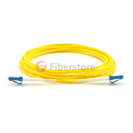
We offer LC fiber cables and LC fiber patch, including single mode 9/125 and multimode 50/125, multimode 62.5/125, LC-LC, LC-SC, LC-ST, LC-MU, LC-MTRJ, LC-MPO, LC-MTP, LC-FC, OM1, OM2, OM3. Other types also available for custom design. Excellent quality and fast delivery.

Talk about LC connector, the common connector type we have seen, there are FC connector, SC connector, ST connector, ect. The following is some connector type features.

FC: A metal screw on connector, with a 2.5mm ferrule, developed by NTT. The ruggedness of this connector leads to its extensive use at the interfaces of test equipment. It is also the most common connector used for PM, polarization maintaining, connections. Please note that there are currently four different specifications for the key width on FC connectors and for the slot width on FC adapters. Therefore not all FC connectors will fit into all FC adapters.

LC: As mall form factor plastic push/pull connector, with a 1.25mm ferrule, developed by Lucent. The LC has been referred to as a miniature SC Connector. It is mainly used in the United States.

MTP: A push/pull ribbon connector, which holds up to 12 fibers. The 12-fiber capacity allows for very dense packing of fibers and a reduction in the number of connectors required.

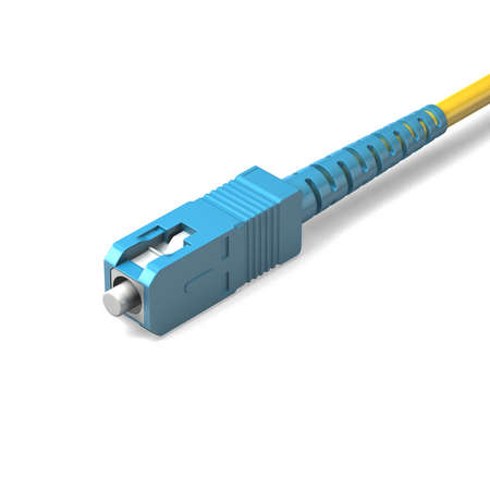
SC: A plastic push-pull connector, with a 2.5mm ferrule, developed by NTT. Push-pull connectors require less space in patch panels than screw on connectors. The SC is the second most commonly used connector for PM, polarization maintaining, connections.

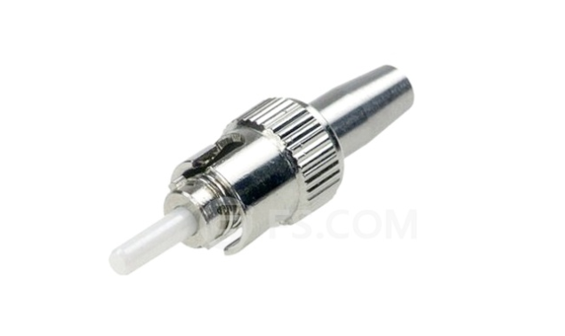
ST: A metal bayonet coupled connector, with a 2.5mm ferrule, developed by AT&T. The ferrule moves as load is applied to the cable in this aging design. There is a version of the ST, which the Navy uses extensively, where the ferrule does not move as a load is applied to the cable.

Fiberstore has a global reputation for bringing best-in-class technology and design concepts to the marketplace. Added to close customer relationships, decades of experience in the industry and outstanding service and support, make Fiberstore the right choice for fiber optic components and systems that will splice your fiber optic components together. We offer fiber optic patch cable, fiber optic cable, fiber optic transceivers, ect. In particular, Fiberstore products include optical subsystems used in fiber-to-the-premise, or FTTP, deployments which many telecommunication service providers are using to deliver video, voice, and data services.

Related Article:  Which Patch Cable Should I Choose for My Optical Transceiver?

Connectorized Couplings

Share

Quite often it is desirable to have a means of connecting two fibers together through a temporary mating device or connector. Figure 7.4 shows a common way to implement such a connector. Each fiber is placed in a ferrule whose function is to provide the mechanical support for the fiber and hold it in place tightly. The ferrule can be made out of plastic, metal, or ceramic materials. The central piece of the connector itself is an alignment sleeve. The two ferrules are inserted in the sleeve, and proper alignment between the cores is ensured because of the tight mechanical tolerances of the ferrules and the sleeve. The gap between the two fibers can be controlled by a mechanical stop which determines the exact stopping positions of the fibers. In some variations, the alignment sleeve is tapered to improve connector mating and demating.

Well-designed connectors provide low coupling loss, in the order of 0.1 dB or less. However, as shown in Fig. 7.5, a number of underirable situations can reduce the coupling efficiency. Figure 7.5a shows a case of two fibers with different core diameters. In general, whenver the numberical apertures of two fibers are different, the potential for power loss exists. In this case, light coupling from a narrower fiber core to a wide fiber core is easier and more efficient compared to coupling in the other direction. Figure 7.5b shows an example of poor concentricity. Fibers that do not provide a tigh concentricity tolerance may show large coupling variations depending on the orientation or from one pair of fibers to the next.

fiber connector

A large air gap, shown in Fig 7.5c, is another reason for loss of power. An air gap can result from incomplete insertion of the fiber or from mechanical problems inside the sleeve. It is also common for microscopic dust particles to get into fiber optic connector, preventing them from making proper conatact, or even scratching and damaging the fiber facets.

More dramatic power reduction results when dust particles land on the fiber core, blocking the light path. As a result, constant monitoring and cleaning of fiber facets are important to prevent such probems. Angular or lateral displacement, the mechanical tolerances are not tigh enough or when the dimensions of the sleeve and the ferrule do not match.

A fiber connector is characterized by several important parameters. As noted before, the most important factor is insertion loss, or simply connector loss. Another important factor is repeatability. If the same two fibers are connected through the same connector a number of times, each time the coupling will be slightly different. A good connector assmbly provides a small standard deviation for coupling efficiency across multiple insertions. Another desiralbe specification of a fiber connector is low return loss, i.e., a low back reflection. Return loss is defined as the ratio of the reflected power from the connector to the input power. For example, a return loss f 30 dB means 0.001 of the input power is reflected back from the connector. A conector must also be resistant and show a minimal coupling variation in the presence of normal mechanical forces such as axial and lateral forces. This is a practical requirement because in a normal environment it is likely for the connector to encounter a range of mechanical forces.

A wide range of connectors have been designed and are in use in the industry. Here we give an overview of some of the most popular types.

Straight tip or ST connectors are one of the more common type of connectors and in wide use in many applications. The ferrule diameter in an ST connector is 2.5 mm. ST connectors are spring loaded and enaged by a twist-and-lock mechanism.

Fixed connector or FC connectors use an alignment key and a threaded (screw-on) socket and are similar to the popular SMA connectors used in electronics. They are in wide use in single-mode applications and provide low insertion loss and high repeatability.

Subscriber connector, or SC, is another common type of connector. The advantage of SC connectors is that they are engaged by a push-and-snap mechanism, without the need for any roation. This make plugging and unplugging them very easy and also reduces wear out. Moreover, a higher connector density is achieved. Many transceivers provide either an SC receptacle connector, or a pigtail SC connector, as their optical interface. The push-and-snap feature of SC connectors thus provides very convenient and easy way of connecting to optical trasceivers. SC connectors are avaiable in simplex and duplex variations. The ferrule diameter in an SC connector is 2.5 mm.

SC fiber optic patch cable is one of the earliest stype and one of the most commonly used fiber optic cable, it is convenient to use and cost saving, SC fiber optic patch cord is widely uesed in fiber optic networks. SC fiber patch cable is with zirconia sleeve and plastic housing. The common type of SC connector patch cord, there are SC to SC fiber patch cord,  SC to LC Fiber Optic Patch Cable, SC to ST Fiber Optic Patch Cable,  SC to FC Fiber Optic Patch Cable, ect.

The LC or small form factor connector is similar to the SC, but with half the size. The diameter of the ferrule in an LC connector is 1.25 mm, vs 2.5 mm for most other connectors. This allow for twice the connector density for a given space. Because of their compactness, LC connectors have become more popular and are used in many high-end transceivers such as SFPs and XFPs.  LC fiber optic patch cable is with a small form factor (SFF) connector and is ideal for high density applications. LC fiber optic patch cord connector has a zirconia ceramic ferrule measuring 1.25mm O.D. with a PC or APC endface, and provides optimum insertion and return loss.

Related Article:  Which Patch Cable Should I Choose for My Optical Transceiver?

Two Main Connector Type: ST vs SC

Share

There are many different fiber optic connection methods, connector types, and ways to terminate them, such as SC connector and ST connector. Single-mode and multi-mode connectors create differences in the types and methods used as well. If you plan to work with fiber optics, you should perform in-depth research about fiber before attempting to terminate it. In fact, it is best to take a course in fiber optic cable termination or learn from an expert. This post will tell you how to choose  ST vs SC connector when terminating fiber and adding connectors.

In addition to the two main connector types of ST vs SC connector, there are many other connection types that have been developed through the years. But to limit the scope of this book to what is most widely used on data networks today, you need to be thoroughly familiar with the ST vs SC connectors.

ST vs SC Connector: Which to choose?

SC Connector

SC type connector is a snap-in connector, meaning that you place it in a receptacle, such as on a network switch, and click it into place; this is also called stick and click. The SC connector is shown in the figure below.

SC connector

SC connector is a relatively new connector-type technology, but are in popular use today. Part of their popularity is that SC connector is cheaper and easier to use than ST connectors, and less prone to damage. You will most likely see these types of connections from large core switches with fiber uplinks to smaller closet switches in campus network.

As we know, SC patch cable is with SC fiber connector which was invented by NTT. It is widely used fiber optic patch cables. SC fiber optic patch cable has low cost and good durability, SC fiber optic patch cables is with a locking tab on the cable termination, it is a push and pull type optical connector. The common SC patch cable we have seen, there are SC to FC, SC fiber optic cable, SC to ST, and SC to LC.

ST Connector

ST connector is another type of fiber connection. Like the BNC connector for coaxial cable, it has a bayonetbased mounting end and a long cylindrical ferrule, which is spring-loaded sheath used to hold the fiber in place. You insert the connector into a receptacle and twist it to lock it into place. Stick and twist considered an older technology, but is still widely used on data networks, and its install base is broad. An ST connector is shown in the figure below.

st-connector

Real-world production environments (especially when working with Cisco Systems, Nortel Networks) do not include ST in new implementations. In most cases, the only way to use this order technology is with a mediation device, such as a transceiver, which has one end that plugs into an attachment unit interface (AUI) port and an ST-based mounting connection on the other end.

Conclusion on ST vs SC Connector

To facilitate installation of our active fiber equipment, we support a large selection of fiber optic patch cords. The always in stock fiber cables are with SC connector, ST connector, LC connector and FC connector type, simplex and duplex. Our patch cords range from 0.5m to 10m and have almost all available combination of optical connectors. The most available lengths are 1m, 2m, 3m, 5m, and 10m patch cords. All single-mode patch cords are UPC polished (Ultra Physical Contact), while the multi-mode cables are PC polished. All fiber patch cords are manually tested and verified and each patch cable is individually sealed and labeled with measured optical performance.We offer competitive price for fiber optic patch cable, our company has strictly quality control system and high quality products,the custom fiber patch cable is fast delivery to worldwide customers.

Related Article:  Which Patch Cable Should I Choose for My Optical Transceiver?

                             How Many Fiber Connector Types Do You Know?

                             How Much Do You Know About Fiber Connector Cleaning? 


Overview of 16 Gbps Fiber Channels

Share

Offering considerable improvements from previous FC speeds, 16 Gbps FC uses 64b/66b encoding, retimers in modules, and transmitter training. Doubling the throughput of 8 Gbps to 1,600 Mbps, it uses 64b/66b encoding to increase the efficiency of the link. 16 Gbps FC links also use retimers in the optical modules to improve link performance characteristics, and electronic dispersion compensation and transmitter training to improve backplane links. The combination of these technologies enables the 16 Gbps FC to provide some of the highest throughput density in the industry, making data transfers smoother, quicker, and cost-efficient.

Although 16 Gbps FC doubles the throughput of 8 Gbps FC to 1600MBps, the line rate of the signals only increases to 14.025 Gbps because of a more efficient encoding scheme. Like 10 Gbps FC and 10 Gigabit Ethernet (GbE), 16 Gbps FC uses 64b/66b encoding, that is 97% efficient, compared to 8b/10b encoding, that is only 80% efficient. If 8b/10b encoding was used for 16 Gbps FC, the line rate would have been 17 Gbps and the quality of links would be a significant challenge because of higher distortion and attenuation at higher speeds. By using 64b/66b encoding, 16 Gbps FC improves the performance of the link with minimal increase in cost.

To remain backward compatible with previous Fiber Channel speeds, the Fiber Channel application specific integrated circuit (ASIC) must support both 8b/10b encoders and 64b/66b encoders.

As seen in Figure 2-1, a Fiber Channel ASIC that is connected to an SFP+ module has a coupler that connects to each encoder. The speed-dependent switch directs the data stream toward the appropriate encoder depending on the selected speed. During speed negotiation, the two ends of the link determine the highest supported speed that both ports support.

The second technique that 16 Gbps FC uses to improve link performance is the use of retimers or Clock and Data Recovery (CDR) circuitry in the SFP+ modules. The most significant challenge of standardizing a high-speed serial link is developing a link budget that manages the jitter of a link. Jitter is the variation in the bit width of a signal due to various factors, and retimers elliminate most of the jitter in a link. By placing a retimer in the optical modules, link characteristics are improved so that the links can be extended for optical fiber distances of 100 meters on OM3 fiber. The cost and size of retimers has decreased significantly so that they can now be intergrated into the modules for minimal cost.

The 16 Gbps FC multimode links were designed to meet the distance requirements of the majority of data centers. Table 2-2 shows the supported link distances over multimode and single-mode fiber 16 Gbps FC was optimized for OM3 fiber and supports 100 meters. With the standardization of OM4 fiber, Fiber Channel has standardized the supported link distances over OM4 fiber, and 16 Gbps FC can support 125 meters. If a 16 Gbps FC link needs to go farther than these distances, a single-mode link can be used that supports distances up to 10 kilometers. This wide range of supported link distances enables 16 Gbps FC to work in a wide range of environments.

Another important feature of 16 Gbps FC is that it uses transmitter training for backplane links. Transmitter training is an interactive process between the electrical transmitter and receiver that tunes lanes for optimal performance. The 16 Gbps FC references the IEEE standards for 10GBASE-KR, which is known as Backplane Ethernet, for the fundamental technology to increase lane performance. The main difference between the two standards is that 16 Gbps FC backplanes run 40% faster than 10GBASE-KR backplanes for increased performance.

Fiberstore introduces it’s new OM4 Laser-Optimized Multimode Fiber (LOMMF) “Aqua” cables, for use with 40/100Gb Ethernet applications. These new technology, 50/125um, LC/LC Fiber Optic cables, provide nearly three times the bandwidth over conventional 62.5um multimode fiber, with performance rivaling that of Singlemode cable, at a much reduced cost. LOMMF cable allows 40/100Gb serial transmission over extended distances in the 850nm wavelength window, where low-cost Vertical Cavity Surface Emitting Lasers (VCSELs) enable a cost-effective, high-bandwidth solution. OM4 fiber optic patch cord is ideally suited for LAN’s, SAN’s, and high-speed parallel interconnects for head-ends, central offices, and data centers. Tripp Lite warrants this product to be free from defects in material and workmanship for Life. Now the following is the OM4 fiber from Fiberstore.

OM4 SC to SC fiber patch cord feature an extremely high bandwidth–4700MHz*km, more than any other mode. They support 10GB to 550 meters and 100GB to 125 meters. These cables are suitable for high-throughput applications, such as data storage. These cables are fully (backwards) compatible with 50/125 equipment as well as with 10 gigabit Ethernet applications. These connectors utilize a UPC (Ultra Physical Contact) polish which provides a better surface finish with less back reflection. With the OM4 cables, you can use longer lengths than OM3 cables while still having an excellent connection.

We offer a huge selection of single and multimode patch cords for multiple applications: mechanical use, short in-office runs, or longer runs between and within buildings, or even underground. Gel-free options are available for less mess, and Bend Insensitive cables for minimizing bend loss, which can be difficult to locate and resolve.

Related Article:  Which Patch Cable Should I Choose for My Optical Transceiver?

Small Form Factor Fiber-Optic Connectors

Share

One of the more popular styles of fiber-optic connectors is the small form factor (SFF) style of connector. SFF connectors allow more fiber optic terminations in the same amount of space over their standard-sized counterparts. The two most popular are the mechanical transfer registered jack (MT-RJ or MTRJ), designed by AMP, and the Local Connector (LC), designed by Lucent.

MT-RJ

The MT-RJ fiber optic connector was the first small form factor fiber optic connector to see widespread use. It is one-third the size of the SC and ST connectors it msot often replaces. It had the following benefits:

● Small size
● TX and RX strands in one connector
● Keyed for single polarity
● Pre-terminated ends that require no polishing or epoxy
● Easy to use

LC

Local Connector is a newer style of SFF fiber optic connector that is overtaking MT-RJ as fiber optic connector. It is especially popular for use which Fiber Channel adapters and Gigabit Ethernet adapters. It has similar advantages to MT-RJ and other SFF-type connectors but is easier to terminate. It uses a ceramic insert as standard-sized fiber-optic connectors do. Figure 1.21 shows an example of the LC connector. Mentioned fiber optic connector, we know fiber optic patch cords, a fiber optic patch cord is constructed from a core with a high refractive index, surrounded by a coating with a low refractive index that is surrounded by a protective jacket. Transparency of the core permits transmission of optic signals with little loss over great distances. The coating’s low refractive index reflects light back into the core, minimizing signal loss. The protective jacket minimizes physical damage to the core and coating.

Connector design standards include FC, SC, ST, LC, MTRJ, MPO, MU, SMA, FDDI, E2000, DIN4, and D4. Cables are classified by the connectors on either end of the cable; some of the most common cable configurations include FC-FC, FC-SC, FC-LC, FC-ST, SC-SC, and SC-ST.

lc to lc fiber patch cord is used to send high-speed data transmissions throughout your network. LC/LC fiber optic cables connect two components with fiber optic connectors. A light signal is transmitted so there is no outside electrical interference. Our LC/LC fiber optic patch cables are 100% optically tested for maximum performance. We have all lengths and connectors available.

Multimode LC/LC fiber optic patch cable send multiple light signals. They are 62.5/125µ. Common connectors are ST, LC, SC and MTRJ. Our 62.5/125µ LC/LC multi-mode fiber cables can support gigabit ethernet over distances up to 275 meters.

Cable Type Summary

common-ethernet

Fiber optic patch cables are used for linking the equipment and components ,we have fiber optic patch cable with different fiber connector types,our low insertion loss and low back reflection .Axen Technologies fiber patch cable is widely applied in Telecommunication Networks ,Gigabit Ethernet and Premise Installations.

Related Article:  Which Patch Cable Should I Choose for My Optical Transceiver?

The Fiber Optic Patch Cord Reliability

Share

Fiber optic patch cords are one of the simplest elements in any optical network, consisting of a piece of fiber optic cable with a connector on each end. Despite its simplicity, the Fiber Optic Patch Cord can have a strong effect on the overall performance of the network. The majority of problems in any network occur at the physical layer and many are related to the patch cord quality, reliability, and performance. Therefore, using patch cords that are more reliable helps reduce the chance of costly network downtime. This article mainy the patch cord reliability.

Network designers would prefer components with a history of proven long-term performance. However, since optical networking is a relatively new technology, there is no significant long-term data for many components. Therefore, designers must rely upon testing from the component manufacturer or supplier that can simulate this history and assure the quality and reliability over the life of the network. This paper discusses the importance of quality, reliability, and performance as they relate to industry standards and manufacturing practices. The performance of the patch cord is also studied using a “perfect patch cord” and polishing observations as tools to understand patch cord principles.

Patch cord reliability is guaranteed not only by using quality components and manufacturing processes and equipment, but also by adherence to a successful Quality Assurance program. While patch cords themselves are typically tested 100% for insertion loss and return loss, if applicable, there are many other factors that need to be monitored to insure the quality of the patch cord.

One of the most important factors is the epoxy. Epoxies typically have a limited shelf life and working life, or “pot life.” This information is readily available from the manufacturer. It is absolutely necessary that both of these criteria be verified and maintained during manufacture. Epoxy beyond its expiration date needs to be discarded. Chemical changes affecting the cured properties of the epoxy can occur after this date. This date can also be dependent on storage conditions, which need to be observed.

Most epoxies used in fiber optic terminations are two-part epoxies and, while they cure at elevated temperatures, preliminary cross-linking will begin upon mixing. Once this has started, the viscosity of the epoxy can begin to change, making application more difficult over time. The epoxy can become too thick to fill the ferrule properly and too viscous to enable a fiber to penetrate, causing fiber breakage.

Many of the tooling used in patch cord assembly also has periodic maintenance and a limited tool life. This includes all stripping, cleaving and crimping tools. Most stripping tools, whether they are hand tools or automated machines, can be damaged by the components of the cable, most notably the aramid yarn strength members. Buffer strippers will dull with prolonged usage, increasing the likelihood that they will not cleanly cut the buffer. This can lead to overstressing the fiber when the buffer is pulled off. When a cleaving tool wears out and a clean score is not made, it is almost impossible to detect during manufacturing. However, the result could be non-uniform fiber breakage during the cleave, which can result in either breaking or cracking the fiber below the ferrule endface. In this instance, the connector will have to be scrapped. Even crimp tools require periodic maintenance to insure the proper forces and dimensions are consistent. Crimp dies also have a tendency to accrue epoxy build-up, which can affect the crimping dimensions and potentially damage the connector.

The integrity of the incoming materials and manufacturing processes, once specified, needs to be adhered to all the appropriate guidelines and procedures. The importance of these materials not only has a strong influence on product reliability, but also on product performance.

Fiber optic patch cords are fiber optic cables used to attach one device to another for signal routing. It compresses in the entire electric network plank and room that wall plank and the flexibility cabinet needs, causes such the person who passes room merely considerably traditional FC,LC,ST and SC’s connection box in parts.Intelligently the bright and beautiful corporation adopts well-developed technique and installation, and carrying on scale manufacture, the produce performance is good, and the quality is steady dependable. Fiberstore manufactures fiber optic patch cables, fiber optic patch cords, and pigtails. There are LC, SC, ST, FC, E2000, SC/APC, E2000/APC, MU, VF45, MT-RJ, MPO/MTP, FC/APC, ST/APC, LC/APC, E2000, DIN, D4, SMA, Escon, FDDI, RoHS compliant, LSZH, Riser,Plenum, OFNR, OFNP, simplex, duplex, single mode, 9/125, SM, multimode, MM, 50/125, 62.5/125; armored fiber optic patch cords, OM4 patch cord, waterproof fiber optic patch cords, ribbon fiber optic cables and bunched fiber optic cables.

Related Article:  Which Patch Cable Should I Choose for My Optical Transceiver?

Core And Cladding In Fiber Optic Cable

Share

Fiber optic cables transmit data through very small cores at the speed of light. Significantly different from copper cables, fiber optic cables offer high bandwidths and low losses with the help of the core and cladding. And it allows high data-transmission rates over long distances. Light propagates throughout the fiber cables according to the principle of total internal reflection.

There are three common types of fiber optic cables: single-mode, multimode, and graded-index. Each has its advantages and disadvantages. There also are several different designs of fiber optic cables, each made for different applications. In addition, new fiber optic cables with different core and cladding designs have been emerging; these are faster and can carry more modes. While fiber optic cable are used mostly in communication systems, they also have established medical, military, scanning, imaging, and sensing applications. They are also used in optical fiber devices and fiber optic lighting.

Fiber optic cable is a filament of transparent material used to transmit light, as shown in Figure 1.2. Virtually all fiber optic cables share the same fundamental structure. The centre of the cable is referred to as the core. It has a highter refractive index than the cladding, which surrounds the core. The contact surface between the core and the cladding creates an interface surface that guides the light; the difference between the refractive index of the core and cladding is what causes the mirror like interface surface, which guides light along the core. Light bounces through the core from one end to the other according to the principle of total internal reflection, as explained by the laws of light. The cladding is then covered with a protective plastic or PVC jacket. The diameters of the core,cladding, and jacket can vary widely; for a single fiber optic cable can have core, cladding, and jacket diameters of 9, 125, and 250 um, respectively.

Figure 1.3 shows the structure of a typical fiber optic cable. The cores of most fiber optic cables are made from pure glass, while the cladding are made from less pure glass. Glass fiber optic cable has the lowest attenuation over long distances but comes at the highest cost. A pure glass fiber optic cable has a glass cladding. Fiber optic cable core and cladding may be made from plastic, which is not as clear as glass but is more flexible and easier to handle. Compared with other fiber cables, Plastic Optical Fiber Cable is limited in power loss and bandwidth. However, they are more affordable, easy to use, and attractive in applications where high bandwidth or low loss is not a concern. A few glass fiber cable cores are clad with plastic. Their performance, though not as good as all-glass fiber cables, is quite respectable.

core and cladding in fiber optic cable

The jacket is made from polymmer (PVC, plastic, etc.) to protect the core and the cladding from mechanical damage. The jackets has several major attributes, including bending ability, abrasion resistance, static fatigue protection, toughness, moisture resistance, and the ability to be stripped. Fiber optic cable jackets are made in different colours for colour-coding identification. Some optical fibers are coated with a copper-based alloy that allows operation at up to 700 and 500℃ for short and long periods, respectively.

Fiberstore is a leading supplier of Fiber Optic Cable and components into the umbilical and towed array products for the oil & gas sector. The key technology for these products is Fiberstore’s patented stainless steel fiber optic tube technology which packages the optical fiber in the best possible way resulting in a robust, compact product that is suitable for the high pressure of the subsea environment. Fiberstore will customize the design to meet your needs to include different fiber counts, fiber types, metal types, tube sizes, belting materials, armor type, armor size, armor count, encapsulation types, color, print, packaging and length.

Related Article:  Which Patch Cable Should I Choose for My Optical Transceiver?

Related Article:  The Advantages and Disadvantages of Optical Fiber

More Characteristics of Fiber Optic Cable

Share

When light from a source is sent through a fiber-optic cable, the ligth wave both bounces around inside the cable and passes through the cable to the outlet protective jacket. When a light signal inside the cable bounces off the cable wall and back into the cable, this is called reflection. When a light signal passes from the core of the cable into the surrounding material, this is called refraction. Figure 3-9 demonstrates the differece between reflection and refraction.

Light can be transmitted through a fiber-optic cable using two basic techniques. The first technique, called single-mode transmission, requires the use of a very thin fiber-optic cable and a very focused light source, such as a laser. When a laser is fired down a narrow fiber, the light follows a tight beam, and so there is less tendency for the light wave to reflect or refract. Thus, this technique allows for a very fast signal with little signal degradation (and thus less noise) over long distances. Because lasers are used as the light source, single-mode transmission is a more expensive techique than the second fiber-optic cable signaling techique. Any application that involves a large amount of data transmitted at high speeds is a candidate for single-mode transmission.

The second signaling technique, called multimode transmission, uses a slightly thicker fiber cable and an unfocused light source, such as an LED. Because the light source is unfocused, the light wave experiences more refraction and reflection (i.e, noise) as it propagates through the wire. This noise results in signals that cannot travel as far or as fast as the signals generated with the single-mode technique. Correspondingly, multimode transmission is less expensive than single-mode transmission. Local area networks that employ fiber-optic cables often use multimode transmissions.

Single-mode and multimode transmission techniuqes use fiber-optic cable with different characteristics. The core of single-mode fiber-optic cable is 8.3 microns wide, and the material surrounding the fiber – the cladding – is 125 microns wide. Hence, single-mode fiber optic cable is labeled 8.3/15 cable. The core of multimode fiber optic cable is most commonly 62.5 microns wide, and the cladding is 125 microns. Multimode fiber optic cable is labeled 62.5/125 cable. Othe sizes of multimode fiber optic cable include 50/125 and 100/140 microns.

Bulk fiber optic cable comes in lots of types, depending on where it will be installed. Where to buy fiber optic cable? As the best OEM fiber optic cable manufacturer, Fiberstore provides a wide range of quality optical fiber cables with detailed specifications displayed for your convenient selecting. Per foot price of each fiber cable is flexible depending on the quantities of your order, making your cost of large order unexpected lower. Customers can also have the flexibility to custom the cable plant to best fit their needs. Only fiber cable that meets or exceeds industry standards is used to ensure quality products with best-in-class performance. Fiberstore offers an extensive line of off the shelf bulk fiber optic cable to address your fiber installation needs. We stock 62.5/125, 50/125, and 9/125 bulk fiber optic cable in simplex, duplex (zip cord), breakout, and distribution styles.

Related Article:  Which Patch Cable Should I Choose for My Optical Transceiver?