Monthly Archives: May 2014

10G Ethernet Transmission MPO System Scheme

Share

June 2002, IEEE802.3ae Task Force issued a series of fiber-based Gigabit Ethernet standard, commonly used in LAN 10GBase-SR/SW as example, 10GBase-SR/SW using serial transmission technology, that is, each core optical fiber only send or receive signals, so to achieve 10Gbps transmission requires at least two-core optical fiber.

MPO fiber optic deployment system has two solutions, one is to use the program with MPO module box, because MPO module box is with metal needles, therefore MPO trunk cables do not need to distinguish whether with a metal pin (Pin), most users tend to use MPO module case scenario; another option is to use MPO coupler, such programs must differentiate between MPO trunk cables with metal needles and without metal pin, the other two ends need to convert Fiber Jumper, so this program is rarely adoption.

According ANSI/TIA-568-C.3 standards are divided into the following two types of duplex Fiber jumpers:

Standard: (A-B)

MPO Fiber

Non-Standard: (A-A)

MPO

According ANSI/TIA-568-C.3 standard, MPO coupler is divided into Type A, Type B two types:

MPO Fiber Connector

MPO Fiber Optic

MPO fiber optic system according to the MPO trunk cables, MPO module boxes and jumpers of different types have different combinations of programs, mainly A, B, C three kinds of channel combination scheme

Method A: Using straight-through (Type A) of MPO trunk cables, Fiber Jumpers must be used at both ends of different models, Scenario A increases the complexity of the orders, it is not recommended to use programs A.

Method B: A fully cross (Type B) of MPO trunk cables, MPO module box must use two different types (Key Up-Key Up) and (Key Down-Key Down), another plan B does not support the ramp octave end face (singlemode fiber, so most manufacturers do not recommend using program B.

Method C: Using lines cross (Type C) of MPO trunk cables, MPO consistent at both ends of the module box (Type A) and standard jumpers, so Option C is the solution of choice for 10G Ethernet recommended.

There are some related MPO products from fiberstore, you can see to know more about MPO Fiber.

12 Fibers, Single-Mode, 12 Standard MPO Fiber Cable,3.0mm LSZH

MPO Trunk Cable

FiberStore offer singlemode and multimode (OM1, OM2, 10G OM3, 10G OM4) MPO/MTP Cable. Singlemode MPO MTP Fiber cable is primarily used for applications involving extensive distances, 10G Mpo Cassettes provide 10 gigabit data transfer speeds in high bandwidth applications and they are 5 times faster than standard 50um fiber cable. Work with both VCSEL laser and LED sources. The meanwhile, we also provide 40G/100G MPO/MTP trunk cable.

The Development of Multimode Fiber Patch Cable

Share

Corning and Lucent and other large companies proposed a “new generation of multi-mode fiber” concept to the international standardization bodies. A new generation of multimode fiber patch cable standards drafted by the International Organization for Standardization / International Electrotechnical Commission (ISO / IEC) and the Telecommunications Industry Alliance (TIA-TR42). As a new generation of multimode fiber transmission medium 10Gb / s Ethernet, be included in IEEE 10Git / s Ethernet standard. This article will briefly describe the new generation of multimode fiber patch cable critical technology.

1.1 The Typle of Multimode Fiber Patch Cable

The new generation of multimode fiber patch cable is 50/125μm, graded-index multimode fiber distribution. The number of this transmission mode Fiber Optic Cables is approximately 62.5μm multimode fiber transmission mode 1/2.5. This can effectively reduce the dispersion of the multimode fiber mode, increase the bandwidth. For 850nm wavelength, 50/125μm Multimode fiber bandwidth is 500MHz.km. Recent experiments confirmed: the use of 850nm vertical cavity surface emitting laser (VCSEL) as a light source in the 1Gb / s rate, 50μm multimode fiber core diameter standard error can be no transfer 1750m, 50μm core diameter multimode fiber can be a new generation of error-free transmission 2000m. In the 10Gb / s down, 50μm core diameter multimode fiber can transmit a new generation of 600m. A new generation of multi-mode fiber is mainly used to support high-speed Ethernet (Ethernet), Fibre Channel (FC) and fiber optic interconnection (OIF). Meanwhile at 10Gbit / s system can transmit 600m, so that it can be used for building backbone and campus backbone extraordinary distance from the middle. In the data center design, within a distance of 100m to support higher speed (40G and 100Gbits / s? Ethernet, 16G and 32Gbits / s Fibre Channel) data transmission requirements.

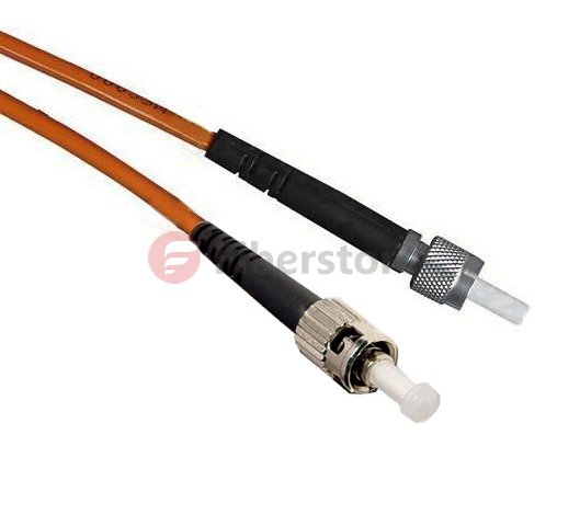
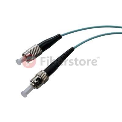
The related products about New Generation multimode mode fiber patch cable, SMA905-ST Duplex 50/125 Dia2.5mm OM2 multimode fiber patch cable from fs.com, the products picture is below:

OM2 Multimode Fiber

The SMA-905 fiber optic patch cord, also known as FSMA connector, was one of the First fiber optic interconnect system that gained industry wide acceptance.SMA905 fiber patch cords make use of threaded connections and is still widely used for military, industrial, medical and Surgical applications and laser systems because of their low cost multimode coupling. It features simple termination and Assembly, and is TIA and IEC compliant. SMA 905 multimode connectors are available with stainless alloy or stainless steel ferrules.

1.2 A New Generation of Multimode Fiber Source

Traditional multimode fiber networks use light-emitting diode (LED) as light source . In low-speed network, which is an economically rational choice. However, LED is spontaneous emission light, the radiation -emitting laser is excited , the carrier lifetime is longer the former than the latter, and thus the LED modulation rate is limited , and not more than gigabit networks. Further, LED compared with a laser, the beam divergence angle, wide spectral width . After injection of multimode fiber , excite more high-order mode, the introduction of more wavelength components, so that the fiber bandwidth decreases . Fortunately 850nm vertical cavity surface emitting laser (VCSEL) not only has the advantage of these lasers, but aslo the price is basically the same with the LED. Other advantages of VCSEL are: low threshold current, may not be enlarged, driven directly by logic gates at 10Gb / s rate, get a few milliwatts of output power; emission wavelength of 850nm which does not apply to the standard single-mode fiber just for multimode fiber . At this wavelength, an inexpensive silicon detectors can be used and have a good frequency response; VCSEL another remarkable advantage is that the manufacturing process can be easily controlled distribution of the emitted light power , which is very advantageous for improving the bandwidth of MMF. It is because of these advantages, the new generation of multimode fiber standard will use 850nm VCSEL light source .

1.3 The Bandwidth Distance of Multimode Fiber Patch Cable

By comparing the above- described laser and LED , the use of multimode fiber laser light source, the transmission bandwidth should be greatly improved. However, experimental results show that simply make the bandwidth of a laser instead of LED light source, system is not only reduced but increased. IEEE Expert Group found through research, the bandwidth of multimode fiber and the optical fiber or the injection molding state of a power distribution. The preform fabrication process, the refractive index of the fiber axis prone to depression. Done before light source LED, is overfilled launch (OFL-Over Filled Launch), all of the fiber mode ( hundreds ) are excited to bring their own part of each module power. The refractive index of the fiber center delay characteristic distortion affects only a small number of models, the relatively limited impact on the modal bandwidth of the fiber. The measured multimode fiber bandwidth for the use of LED light source system is correct. However, when a laser light source, a laser beam spot is only a few microns, the divergence angle is smaller than the LED, so that only a small number of modes excited in the center of the fiber transmission, each mode carries a large part of the power, the refractive index of the fiber center distortion affect a small number of patterns of delay characteristics, so that decreased multimode fiber bandwidth. So it can not be measured with a laser light source for multimode fiber OFL bandwidth of conventional methods.

Today a new generation of multi-mode fiber main measurement bandwidth limit die by injection method (RML-Restricted Mode Launch). In this way the measured bandwidth is called ” laser -bandwidth ” or ” modal bandwidth limit “, previously done with the LED light source measured bandwidth is called “OFL bandwidth is .” Both represent the bandwidth of multimode fiber laser and LED light source with a time of injection. August 5, 2009, TIA Standards Committee released a new generation of bandwidth distance product standard multimode fiber , 850nm laser distance -bandwidth product of 470MHz.km, 850nm OFL bandwidth of distance product of 350MHz.km, 1300nm OFL bandwidth of distance plot to 500MHz.km. Incidentally, the bandwidth from the product of the above-described generation of the multi-mode fiber is only 3dB corresponding baseband bandwidth of multimode fiber, multimode fiber does not take more than a high-frequency band -pass region is also used when the transmission signal . Today, by orthogonal frequency division multiplexing (OFDM) technology , can make good use of multimode optical fiber through a high frequency band region , under conditions of use of the same fiber optic patch cable type, transmission using high frequency band signal through region greatly improved multi-mode fiber transmission capacity.

1.4 Source Injection Method

In actual use, the multimode fiber coupled laser and the following methods:

Bias injection: In order to avoid the deterioration of these lasers is injected directly into the bandwidth MMF appears, use the mode regulator
Connection (MCP Mode Conditioning Patch Cable), the laser output is coupled into a multimode fiber. Connection-mode regulator is a short Single Mode Fiber Cable, one end of which is coupled with the laser and the other end coupled to a multimode optical fiber. SMF output spot detouring from the multimode fiber axis at a distance, allowing the deviation from the range is 17 ~ 24μm, the aim is to avoid the center of the refractive index depression, but do not deviate too far, only one group is selectively lower-order mode excitation .

Centre injection: ideal for the refractive index profile, there is no central depression MMF can be used instead of the center of the injection molding
Regulator connection. The advantage of this is that the bandwidth of the laser can effectively improve the MMF to reduce the complexity of the network system and reduce system cost, a current-mode regulator 80 to the connection of approximately U.S. $ 100. Corning launched InfiniCor CL 1000 (62.5μm core diameter) and InfiniCor CL 2000 (50μm core diameter) is Gigabit Ethernet 1300nm wavelength laser directly into the mode without adjusting the first multi-connection mode fiber.

The Knowledge Of Fiber Optic Cables

Share

The Basics Knowledge Of Fiber Optic Cables

1.1 What is Fiber Optic Calbe?

The fiber optic cable mainly consist of a protective plastic sleeve and plastic sheath structure, no internal cable gold, silver, copper and aluminum and other metals, usually no recycling value. Fiber Patch Cables is a certain amount of the composition according to a certain way of cable core, outsourcing has a jacket, and some also cover the outer sheath to achieve a communication line optical signal transmission. It is the optical fiber cable (optical transmission medium) after the formation of a certain process.

1.2 The factors that affect fiber performance and lifetime

A) Stress: Causes fiber breaks or attenuation increases
B) Water and moisture: the fiber is easy to break (brittle), the impact of life
C) Hydrogen (pressure): the role of a fiber having a hydrogen pressure of mutated fiber attenuation curve of the absorption peak at 1240nm, 1310nm, and the attenuation significantly increased at a wavelength of 1550nm.

1.3 Classification of fiber optic cable

A) By fiber optic cable in the state in points: tight structure, loose structure, semi-loose semi-tight structure
B) By the cable core structure: central tube, Stranded, skeleton, Mode Conditioning Patch Cable, MPO Fiber cable.
C) By the conditions of the cable laying: aerial, pipeline, buried and underwater fiber optic cable
D) By the condition of the use of fiber optic cable with the different types: Single Mode Fiber Patch Cable, Multimode Fiber Cable.
E) By the Environment occasion of using fiber cable: outdoor cables, indoor cables.

1.4 The basic properties of fiber optic cable

Transmission characteristics of the cable depends on the coated fiber. Mechanical properties of the fiber optic cable requirements and environmental characteristics determined by the conditions of use. After the cable production out of the main items of these features, such as tension, pressure, torsion, bending, shock, vibration and temperature, to do routine testing in accordance with national standards. Finished cable is generally required to give the following characteristics, parameters of these characteristics can be analyzed to calculate the empirical formula, here we only briefly qualitative description.

1) The characteristics of Tensile properties

Maximum tension cable can withstand depends reinforcement material and cross-sectional area, generally require more than 1km cable weight, most cable at 100 ~ 400kg range.

2) The characteristics of Pressure

Side cable can withstand the maximum pressure depends on the material and structure of the sheath, most of the cable can withstand the maximum pressure side 100 ~ 400kg/10cm.

3) Bending properties

The main characteristics of bending depends on the material and structure of the core, the cladding and the relative refractive index difference cable. Practical minimum bend radius optical fiber is generally 20 ~ 50mm, the minimum cable bend radius is generally 200 ~ 500mm, equal to or greater than the minimum bend radius of the fiber. Under the above conditions, the fiber of optical radiation caused by the additional loss can be ignored, if less than the minimum bending radius, the additional loss increased dramatically.

4) Temperature properties

Fiber itself has good temperature characteristics. Cable temperature characteristics of design choice and depends on the configuration of the cable material, the temperature characteristics optical fiber which use of secondary coated loose tube cable is better. When the temperature changes, the optical fiber loss increases, primarily due to the cable material (plastic) than the coefficient of thermal expansion of the fiber material (quartz) 2 ~ 3 orders of magnitude, in the thermal expansion or shrinkage process, the fiber produced by the stress. In China, the use of temperature requirements for fiber optic cable, usually in the low-temperature region of -40 ℃ ~ +40 ℃, high temperature region is -5 ℃ ~ +60 ℃.

1.5 Cable moisture measures

A) Radial waterproof – fiber cream and jelly filled cables, metal belt longitudinally, PE jacket

B) Axial waterproof – fiber cables cream and cream filling, water blocking ring, waterproof tape, water blocking yarn, single core strengthening

Know more knowledge of fiber optic cables, you can go to fs.com. fs.com is leading manufacturer and supplier of fiber optic cable products such as fiber optic patch cables, MPO Fiber cable, fiber optic pigtails, fiber optic attenuators, fiber optic connectors, fiber optic adapters, fiber optic transceivers and much more. Every product manufactured by us, is put through stringent quality control standards and procedures to provide only premium quality product to the client. As such our fiber optic patch cords are guaranteed to meet and also go beyond the expectations of the customers.

FAQ In Fiber Optic Cabling

Share

Firstly, do choose multimode or single mode fiber? What is the difference between them?

In general, the user requests the fiber transmission distance is relatively short, such as a few hundred meters, can be Multimode Fiber Optic Cable. However, if the transmission distance has several kilometers, even further, without the use of signal repeaters must be single-mode fiber.

Secondly,  Do choose 4 core, 6 core, 8 core or more core Fiber Optic Patch Cables?

Fiber complete the transfer task, it must receive at least one first serve two core. In fact, there are 4,6,8 or more optical fiber core, the core can be used as extra backup, you can do more transmission channels.

Thirdly,  Does use wall or rack-mounted fiber optic patch panel cable box?

Wall fiber boxes are generally used in small fiber-optic network, for example, a 4-core optical fiber, but if there is more number of fiber optic, it shows the advantages of rack patch panel. It can be placed inside the routers and switches with a cabinet for easy centralized management and more secure.

And then, What is the connector type of FC,SC,ST,LC,MTRJ, and Which one can be choose?

These different interfaces have used in different environments, they differ mainly in the method and shape connection, is it the same as the screws tighten or direct card? Is square or round? Large or small mouth opening (mouth relatively large place occupied by a small mouth can have greater port density)? Two heads separately or synthetic one? Users need not be too concerned about the specific interface, to note that if the extension already exists in the case of older fiber optic systems, you have to match each job.

Finally, Is the choice of the center beam tube or Stranded cable?

Central tube Fiber Optic Cable placed in the center portion of the cable core, many of the core tube synthesis bunch shape, and the outer cable surrounding two wires placed in parallel to ensure tensile strength.

The central part of Stranded cable strengthen stereotypes core fiber. Fiber core surrounded by a peripheral that strengthen the core, many cores together to form the shape layer by layer.

How to identify fiber optic, is single mode or multimode fiber?

The first is a relatively simple method for indoor fiber, it can be identified by single-mode fiber and multimode fiber external color, Single Mode Fiber Cable is yellow, Multimode Fiber Optic Cable is red. Including Fiber optic patch cords and Fiber pigtails are the same recognition.

For MPO Fiber, generally can be identified by model code, there are a bunch of characters on the cable sheath, such GYXTW-4-A1a, the last paragraph begins with A on behalf of the multi-mode fiber, beginning with B represents a multi-mode fiber, a little more detail, A1a representing 50/125 multimode fiber specifications, A1b representatives 62.5/125 multimode fiber specifications, B1.1 representatives of non-dispersion shifted single-mode fiber and so on.

If this way can not be identified single mode fiber or multimode fiber, it is only through a special device to identify, as fiber splicing machine, it will automatically recognize the single mode or multimode fiber, single mode will show SM, multi-mode will show MM.

The Basic Knowledge of Optical Fiber and Pigtail

Share

How do fiber optic work?

Optical fiber communications composed of thin glass by the plastic protective overcoat layer. Glass essentially consists of two parts: the core diameter of 9 to 62.5μm, a low refractive index outer cladding diameter of 125μm glass material. Although according to the different materials
used, there are some other types of fiber, but is mentioned here that the most common types. Light in the core portion of the fiber to the “total internal reflection” mode transmission, but also refers to the light entering end of the fiber, the interface between the core and the cladding reflected back and forth, and then transmitted to the other end of the fiber. Core diameter of 62.5μm, outer cladding diameter of 125μm fiber called 62.5/125μm fiber.

What is the difference between multimode and single-mode fiber?

Multimode Fiber Optic Patch Cables

Almost all of the Multimode Fiber Optic Patch Cables dimensions are 50/125μm or 62.5/125μm, and the bandwidth (the amount of information transmission fiber) is usually 200MHz to 2GHz. Multimode optical transceiver via multimode fiber can be up to 5 km of transmission. In the light emitting diode or a laser light source.

Single Mode Fiber Cable

The size of Single Mode Fiber Cable 9-10/125μm, and compared with a multimode optical fiber, it has unlimited bandwidth and low loss characteristics. The single mode optical transceiver used for long-distance transmission, and sometimes up to 150-200 km. Using a narrow spectral line LD or LED as a light source.

Single mode fiber is cheap, but compared to multi mode fiber device, it is more expensive. Single-mode devices typically can run on single mode fiber, but also be run on a multi mode fiber, and multimode device only runs on multimode fiber.

How is the loss with using of the Fiber Optic Patch Cables?

It depends on the the wavelength of the transmitted light and the kind of optical fiber

When 850nm wavelengths for multimode fiber: 3.0 dB / km
When 1310nm wavelength for multimode fiber: 1.0 dB / km
When 1310nm wavelength for single mode fiber: 0.4 dB / km
When 1550nm wavelength for single mode fiber: 0.1 dB / km

Fiber Optic Pigtails

Fiber Optic Pigtails ony has one end connector, and the other end is an optical fiber core breakage, by fusion connected with other core cable, often appear in the fiber optic terminal box for connecting cable and fiber optic transceivers.

Fiber optic pigtails devide into multimode and singlemode fiber pigtails. Multimode fiber pigtail is orange and wavelength of 850nm, the transmission distance of 500m, for short-range connectivity. Single mode fiber pigtail is yellow, there are two wavelengths, 1310nm and 1550nm, transmission distance of 10km and 40km.

Fiber optic pigtail connector was devided into single mode and multimode by the mode of fiber optic cable; By overall structure can be divided into FC, SC, ST, MU, LC, F25, etc. By the end structures can be devided into PC、UPC、APC.

Here are some fiber optic pigtails products in fs.com, as shown in figure:

Multimode LC/SC/ST/FC Pigtail

Multimode LC/SC/ST/FC Pigtail

ingle-mode LC/SC/ST/FC Bunch Pigtail

Our fs.com provide wide degree flexibility on fiber pigtails, including 9/125 single-mode, 62.5/125 multimode 50/125 multimode and 10G 50/125um OM3 types, simplex fiber, 4 fibers, 6 fibers, 8 fibers, 12 fibers, 24 fibers, 48 fibers and so on.These fiber pigtails can be with fan-out kits and full compliant to Telcordia, EIA/TIA and IEC standards. Welcome to our store to know more information.

Development and Benefits of Multi Core Single Mode Fiber

Share

1. The development of multi core single mode fiber

A typical optical fiber is single mode fiber structure, the outer cladding / inner cladding surrounding the core constitutes a waveguide. A common multi core single mode fiber includes a number of cores, and each core has their own single mode optical fiber inner cladding. Thus, each core is a fiber optic of the waveguide, i.e., one single mode fiber optic cable’s function is equal to a plurality of single core fiber. The obvious advantage of this fiber is low cost, low production costs of about 50% compared with ordinary fiber. In addition, Fiber optic cables can increase integration density, but also can reduce construction costs. Back in the late 1970s, foreigner proposed the idea which uses multi-core optical fiber manufacturing high density fiber. However, because of the imperfect manufacturing technology, fiber affected by the residual stress, low mechanical strength, poor reliability, has not developed into practical and commercialization. Into the 1990s, fiber optic communication in the FTTH ( fiber to the home ) development has encountered higher cost of obstacles, and the intense competition in the copper. To overcome this obstacle, we must significantly reduce the cost of fiber optic cable manufacturing, and requires the development of high-density large armored fiber optic cable, in order to facilitate the laying of fiber optic cable and reducing installation costs. Thus, in 1994, France Telecom proposed a new concept of multi core single mode fiber and design a 4 core fiber optic cable. In July 1994 made more than 100 kilometers Single Mode Fiber Cable, and use different core and structures fiber optic cables and non-fiber ribbon cable into the cable experiment. Compared with the common Single Mode Fiber, the cable density increase many times. Initially confirmed that the proposed multi core single mode fiber can reduce manufacturing costs while addressing the fiber optic cable and the development of high- density optical fiber optic cable. Since then, France Telecom and Alcatel have carried out a 4 core single mode optical fiber research and development , studied from optical design, perform manufacture, drawing techniques, optical properties, a 4-pin cable, and mechanical connections from each a core of separation and termination of ordinary single mode fiber and other aspects of a comprehensive. Currently, the cost per meter per core for $ 0.03, while the cost per meter of ordinary single mode fiber is $ 0.055. We can say that multi-core single mode fiber forward practical development. This article focuses on the structure of multi-core single mode optical fiber design, manufacturing processes, and fiber properties, but also a brief introduction to the new fiber optic FTTH applications in the technical and economic advantages.

2. Design of multi core single mode fiber

To meet the needs of FTTH systems. The design of multi-core fiber should meet the following key requirements: 1.31 um and 1.55um wavelength dual-window work; Crosstalk between each core is greater than -35 dB: precise geometry; Easy identification of each core and ordinary Single mode Fiber Optic Cable. Further, since the optical fiber length shorter in FTTH network (≤ l0 km), so the requirements for dispersion and attenuation of the fiber is relatively relaxed, there are strict requirements on bending and micro bending losses. Each of the core is respectively located on the vertices of a square, the center of the square is the central axis of the multi core single mode fiber. Each core is a single mode optical fiber waveguide, cutoff wavelength 1.3 um. In order to reduce the bending loss and crosstalk, reinforce fiber molded capacity constraints, therefore compared with the conventional G652 optical fiber, the refractive index difference has increased. 3 core is a simple step structure, a refractive index difference 0.0062; another annular core refractive index profile, the refractive index difference 0.0l, this core is provided in order to facilitate identification of each of the cores.

The main advantage of multi core Single Mode Fiber Cable

1. Attenuation coefficient

By the testing and research of nearly 200km long fiber, the attenuation coefficient of the multi core single mode optical fiber reached levels close to the corresponding single core fiber.

2. Bending and micro-bending loss characteristics

Bending and micro bending loss characteristics of the multi-core single mode fiber optic are good, negligible additional loss introduced. This is due to the higher refractive index and limits the ability of a strong mold. Multi core single mode fiber optic in the l310nm and 1550nm wavelength mode field diameter was 8.4 ± 0.21un and 9.75 ± 0.25um, slightly smaller than the ordinary single mode optical fiber.

3. Crosstalk characteristics

To 30 g of tension around 15 cm in diameter optical fiber on ferrule l0 km optical fiber with characteristic measurement, crosstalk between each core at l 310 nm wavelength, less than-70dB; at 1 550 nm wavelength, less than a 50 dB, are excellent -35 dB in the required index. Even slim to the 30 km, between 0-30g tension variations, changes, crosstalk is also only a few dB.

4. Mechanical strength

With 10m length test, the average intensity of 70N. The conventional 125um fiber diameter of 60 N, it is because of a large cross-sectional area of multi-core single mode fiber. Fracture stress 4.6 GPa, 94% for the conventional 125 um diameter fiber.