Monthly Archives: October 2013

MTP VS MPO: What’s the Difference?

Share

In regard to multi-fiber connector, many will think of MTP connector while the others will think it is MPO connector. In most cases, these two kinds of connectors can be considered the same. Actually, they are a little different not only in names but also in some other aspects. MTP VS MPO: what’s the difference? This post will clarify the differences between these two.

MTP VS MPO: What’s an MPO Connector?

As the industry acronym for “Multi-fiber Push On”, MPO is developed to provide multi-fiber connection in one connector to support higher bandwidth and higher density applications. MPO connector is standardized in the international regulatory framework (the IEC 61754-7 standard) and the U.S. (TIA-604-5 Standard ). At present, the most common fiber counts are 12 and 24, and 48 to 72 fiber counts are also possible in limited applications.

mtp vs mpo

MTP VS MPO: What’s an MTP Connector?

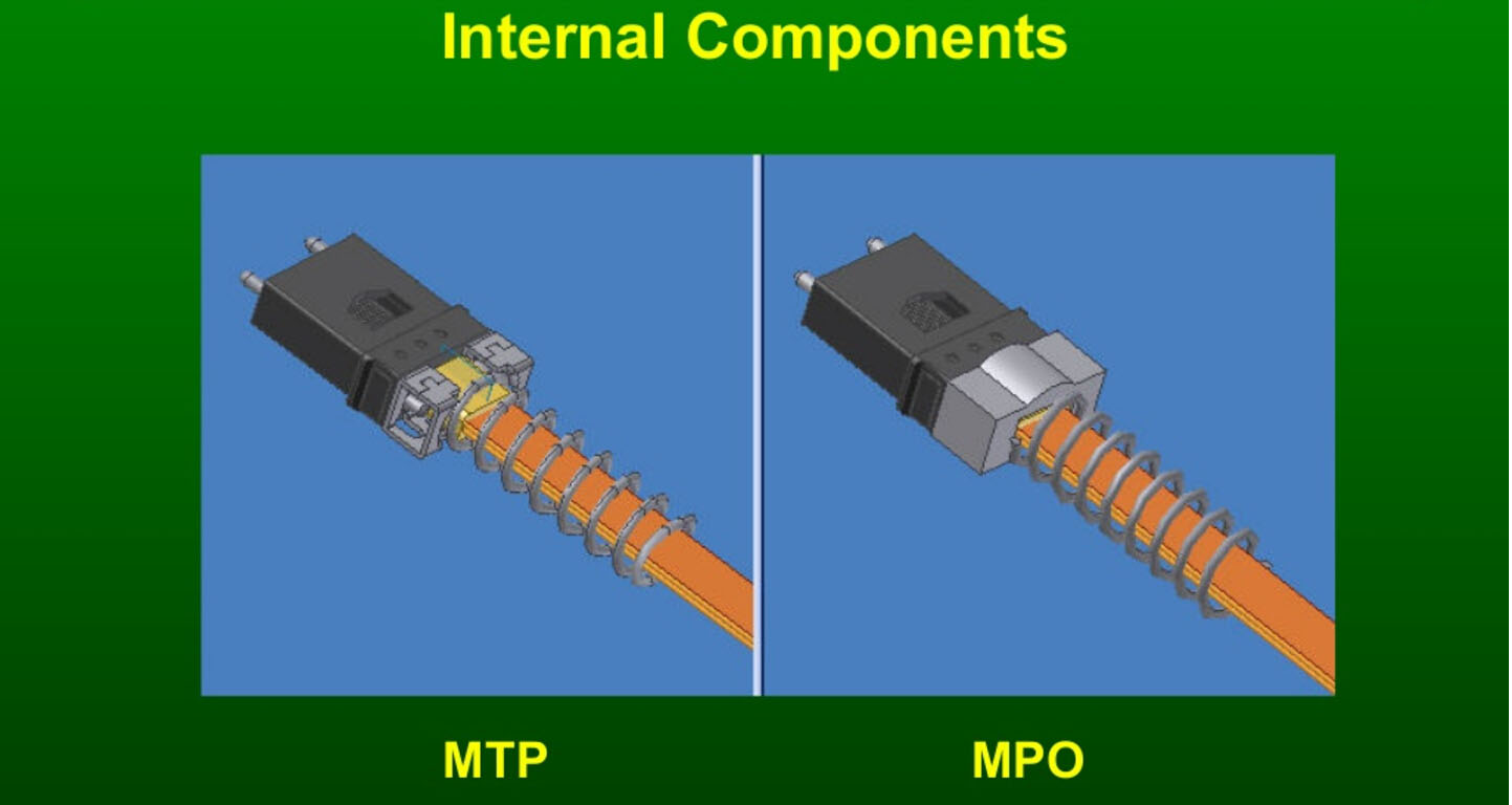
MTP is a registered trade mark of US Conec. In other words, MTP connector is used by US Conec to describe their multi-fiber connector initially. Now MTP is commonly referred to as a high performance MPO connector. So MTP connectors are fully compliance with all generic MPO connectors and can interconnect directly with other MPO based infrastructures.

MTP VS MPO: What’s the Difference?

As mentioned above, MTP connector is an enhanced version of MPO connector. This means Generic MPO connectors are limited in performance and are not able to offer the high performance levels of MTP connectors. Generally, MTP connectors are superior to generic MPO connectors in the following aspects:

Mental Pin Clamp

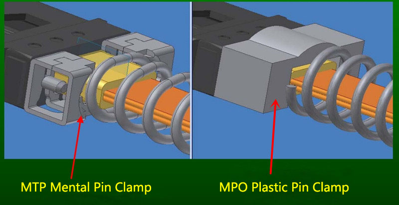
The MTP connector has a metal pin clamp to ensure a strong clasp on the pins and minimize any inadvertent breaking when mating connectors. While MPO connectors are often manufactured with inferior plastic pin clamps which may lead to effortless breaking of pins with constant cable mating.

MTP VS MPO: pin clamp

Floating Ferrule

An important feature of MTP is its floating ferrule, which will help to improve mechanical performance. To be specific, The MT ferrule of MTP connectors can float inside to keep physical contact over a mated pair under an applied load. Generic MPO connector do not have this ferrule float feature.

Elliptical Shaped Guide Pins

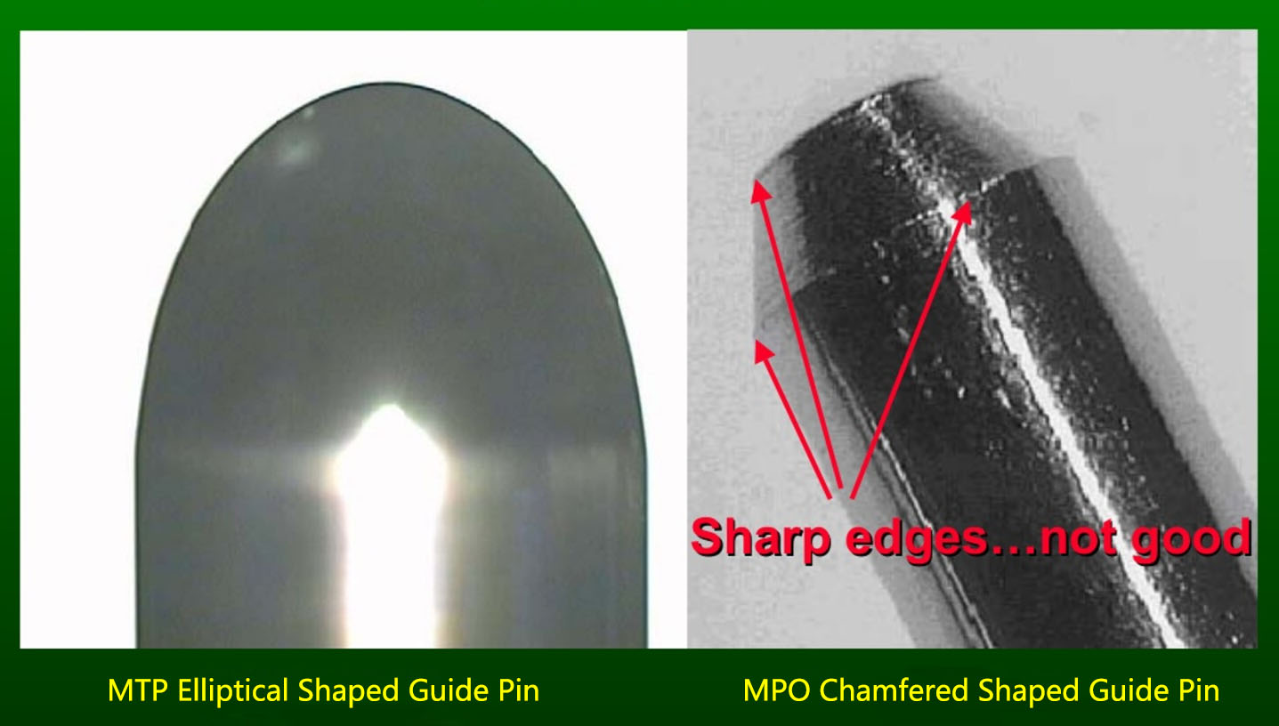
MTP connectors use tightly held tolerance stainless steel elliptical guide pin tips to reduce guide hole wear. Unlike single fiber connectors, the adapters for multi-fiber connectors are only for coarse alignment. Thus the guide pins are critical for accurate alignment when mating two MT ferrules. The elliptical shaped pins of MTP connectors does not chip the ferrule material which helps to reduce the amount of debris that may fall into the guide pin holes or on the ferrule end face. Generic MPO connectors have chamfered shaped guide pins which will produce more debris when used.

MTP VS MPO: guide pin

Removable Housing

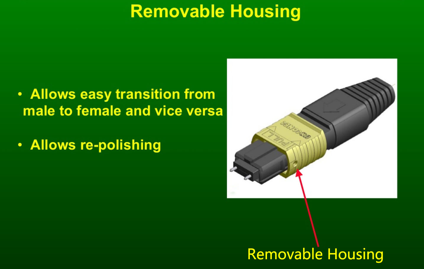
The MTP connector is designed to have a removable housing. This allows users to re-work and re-polish the MT ferrule, to easily get access to performance testing and to smoothly change the gender after assembly or even in the field.

MTP removable housing

Higher Optical Signal Performance

The generic MPO connector is recognized as an international standard for network architects who require density and strive for shorter install times, as well as simplified cabling infrastructure for their 40G/100G data centers. However, in higher fiber count MPO cabling, using MPO connectors will have problems with optical loss (measured in dB), dropped packets and diminished network visibility.

The MTP connector is a high performance MPO connector with multiple engineered product enhancements to improve optical and mechanical performance. It is designed to ensure the precision alignment of the female and male sides. This is critical to reducing insertion loss and return loss in dense, multi-mode fiber connectivity. MTP/MPO connector

Conclusion

MTP VS MPO: Do you know the differences between them now? They are both widely used in high density cabling networks, especially in 40G/100G data centers. MPO is an internationally recognized standard interface for connector manufacturers. While MTP is one type of MPO connector. It is a brand owned by US Conec. If you are planning to build a multi-fiber network, a cable with MTP connectors will give you the best over-life performance. MPO connectors will also work, but may not perform to the same level.

Related Article: MTP/MPO Connector: Difference And Cleaning Recommendation

                           MTP/MPO Cable Assembly – the Game Changer of Data Center Cabling


Types Of Fiber Optic Patch Cable

Share

From the wiki we realize that, Fiber Optic Patch Cord is a fiber optic cable capped at either end with connectors that enable that it is rapidly and conveniently connected to CATV, an optical switch, or another telecommunication equipment. Using a thick layer of protection, it really is used to connect the optical transmitter, receiver, and also the terminal box. This is what’s called “interconnect-style cabling”. Fiber patchcord is the better choice for CATV, Telecom Server, Subscriber Loop, Fiber-to-the-home, and Local Area Network (LAN) applications.There’s another type of fiber cable assembly called Pigtail, it is a short optical fiber permanently attached with a resource, detector, or other fiber optic device at one end and an optical connector on the other. Fiber optic pigtails tend to be for optical device connectivity.

Fiber Optic Patch Cords are created to interconnect or cross connect fiber networks within structured cabling systems. The fiber patch cables types including common single-mode 9/125, OM1 62.5/125, OM2 50/125, 10G OM3/OM4 patch cables, armored patch cables, fiber optic pigtails, multi core patch cables, Fiber MPO/MTP patch cables and other special patch cables. The fiber patchcord are available with the SC, ST, FC, LC, MU, MTRJ, E2000, APC/UPC terminations optical connector. Typical fiber connector interfaces are SC, ST, and LC in both multimode or single-mode applications. Fiberstore supply fiber optic patch cable with different connector and cable type, so we can also customize patch cables in a cut length.

Fiber optic patch cable types:
A fiber patch cords consists of 2 major parts: Optical connector and fiber optic cable.
1)By Optical connector:
LC fiber patch cable; FC patch cable; SC fiber cable; ST patch cable; MU fiber patch cable; MTRJ patch cord; E2000 patch cable; MPO fiber cable.
2)By fiber optic cable types
Single mode fiber optic cable: Generally in yellow color and useful for long transmission distance;
Multimode fiber optic cable: Generally the multimode patch cable are orange or gray and therefore are used for short distance transmission.
3)By fiber optic cable Jacket
PVC: Non-Flame Retardant;
LSZH : Low smoke zero halogen, Flame Retardant

Fiber optic patch cable features:

  • Fiber optic connector type: LC, FC, SC, ST, MU, MTRJ, E2000,MPO
  • Ferrule Interface type: PC, UPC, APC
  • Fiber cores: Simplex, duplex, 4 fibers, 8 fibers etc.
  • Fiber type: Single mode (G.652, G655), multimode(50/125)/(62.5/125)
  • 100% Insertion Return Loss, End Face and Interference inspection
  • Low insertion loss, high return loss
  • Excellent mechanical endurance
  • Insertion loss: <0.5 dB
  • Operation temperature: -20?? to 85??C
  • 10G OM3 OM4 fiber cable available
  • Various jacket material, PVC and LSZH

Fiber optic patch cable applications:

1. Optical Fiber Communication Systems
2. Optical Access Network
3. Fiber optic data transmission
4. Optical Fiber CATV
5. Lan (LAN)
6. Test Equipment

For those who have questions about fiber patch cords or desire to customize fiber patch cables, pls visit our FiberStore website and click on the live chat around the right corner, we will be A day online to assist you solve your problem.

The Knowledge About Underground Wire Tracer

Share

Why need the underground cable locator in our life. Because more and more underground cable as for the load was increased, their own aging and barbaric construction lead cable often fails is not the normal power supply, thus affecting the living and plant shutdowns, immeasurable loss is caused by the mining and other research units.Now an underground cable locator tester can help you to find the question cable.

FiberStore Underground Wire Tracer NF-816 can be used for testing different types of faults in cables like continuity, dislocation, open circuit, short circuit, cable pairing faults, or indications like shielding indication, straight cable/ cross over cable indication, etc. It can help us quickly to find the questions of the fiber optic cable.

About Underground Wire Locator:

The Underground Wire Tracer/Underground Cable Locator is designed to locate the path of non-energized wires behind walls and underground. The 816 is also capable of locating a specific circuit breaker, pinpointing wires before drilling and verifying dig sites underground. The effective range is up to 3 feet deep and up to 1000 feet in length.

Since its development, the unit consists of a transmitter, model 816T, is equipped with a thumb wheel switch for turning the unit on and adjusting the output level on the front of the unit for use with the large alligator clip leads. Push the switch to select to test”Cable Scan” or”Battery Test” The transmitter is constructed of high impact plastic and is powered by one 9V battery.

The receiver, model 816R, is equipped with a thumb wheel switch for turning the unit on and adjusting the receiver gain. The tracking antenna is attached to the receiver with a 3-foot long cable(such as Cat 7 patch cable). Also is equipped with a White LED light and a external earphone, The receiver has been designed to filter AC power related noise. The receiver is constructed of high impact plastic and is powered by one 9V battery.

The alligator clip leads are available to connect the transmitter to electrical wire, CATV coax, telephone drops, irrigation control wires or metallic pipes.

This locating system is packaged in a toolkit & box with extra batteries, external earphone and has operating instructions in the behind of the toolkit.

Key Features

  • Find wire on all types of connected operating Ethernet switch /Router/PC terminal
  • Rapidly find the target wire from among plenty of telephone wires
  • Rapidly find the target wire from among plenty of network wires
  • It can take place of cable tester
  • Compare the volume of the “tout” sound and the brightness of the signal indicator. Then you can find the target wire which has the highest volume and brightest indicator

Functions

  • Trace telephone wire/LAN cable
  • Trace wire in electrical system
  • Verify LAN cable condition
  • Continuity test
  • DC level testing function
  • Bright white LED flash light

Specification

  • Output voltage(open circuit): 9Vp-p
  • Carrier: 44.75KHz
  • Audio modulation: 900HZ
  • Battery: 9V DC
  • Battery Life (nominal):816T (35 hrs); 816R (20 hrs)
  • Size: transmitter: 49*125*33 mm receiver: 43*168*27mm
  • Color: yellow+ black

If you need any work that might risk you running into an electric cable, do yourself a favor and check first with the help of an underground wire tracer. For more info about Underground Cable Locator NF-816, or need some cheap fiber optic cable. Please contact the sales via sales@fs.com, we will answer your questions as soon as possible.

Fiber Optic Media Converters Used In Ethernet Networks

Share

About Fiber Optic Media Converter:

A fiber optic media converter is a simple networking device, the fiber to ethernet media converter can converts one network media type (defined by the cable, connector, and bandwidth) into another. They are also used in metropolitan area network (MAN) access and data transport services to enterprise customers. This transition allows any business, no matter what its size, to expand their old network with the latest technology. This flexibility allows for a greater efficiency and harmony between departments and individuals.

A typical media converter is made up of two transceivers, sometimes referred to as media attachment units. These can transmit data to and from each other. Each MAU (Media Attachment Unit) comes with a different industry standard format fibre connector which is able to join different types of media. The basic concept is that one media type enters and another exits. All connectors are up to date with the latest IEEE standards and protocols.

Benefits of Ethernet to Fiber Optic Converters:

  • Protects your investment in existing copper ethernet-based hardware
  • Provides you with the flexibility to add fiber on a port-by-port basis
  • Enjoy the benefits of fiber without have to make wholesale changes
  • Fast ethernet or Gigabit ethernet to multi-mode or single mode
  • Ethernet to fiber and fiber back to ethernet links
  • Create copper-fiber connections with fiber switches

Why used the fiber to ethernet media converter?

Fiber to Ethernet Media Converter models that are best suited for enterprise and Service Provider applications, offer an on-board processor to continuously monitor that both fiber connections are up. This functionality, generally referred to as “Link Pass-Through”, monitors the state of the link to the end devices and ensures that each end-point knows whether the entire link is up or not. Some media converter products do not have this intelligence and simply “nail up” the link even though the fiber link peer is down. With Link Pass-Through, a feature available in all FiberStore Fiber to Fiber Optic Converters, the network’s SNMP management system can be alerted when a fault occurs so that corrective action can take place.

Fiber to ethernet network media converters are used in Cisco Systems, IBM, Nortel, Microsoft and ADC. By using our media converters, these world leading enterprises cut their cabling cost. Based on Transition Point System advantages, users could save the cost while do not degrade the network performance.

FiberStore is an professional manufacturer & supplier of fiber to Ethernet converter and fiber optic cable. All of our fiber media converters are tested in house prior to shipping to guarantee that they will arrive in perfect physical and working condition. If you have questions about optics(such as customized the fiber to ethernet converter,fiber optic cable specifications,ect.), please feel free to contact us at sales@fs.com.

GEPON Splitter Of Passive Optical Components

Share

With the growing demand of broadband, Passive Optical Network (PON) is the most promising NGN (Next Generation Networking) technology to meet the demand currently. GEPON(Gigabit Ethernet Passive Optical Network) use WDM technology and it is with 1Gbps bandwidth and up to 20km working distance, which is a perfect combination of Ethernet technology and passive optical network technology.

GEPON Technology:

The GEPON (Gigabit Ethernet Passive Optical Network) system is composed of the Optical Line Terminal (OLT), Optical Distribution Network (ODN) and Optical Network Unit (ONU).The ODN consists of only passive elements splitters, fibre connector and fiber optics. PON means passive optic network, EPON is integrated with Ethernet technologies, and GEPON is a Gigabit EPON. GEPON system is designed for telecommunication use. This series of products features high integration, flexible application, easy management, as well as providing QoS function. The fiber network speed can reach up to 1.25GB/s and each EPON OLT (Optical Line Terminal) system can distribute into 32 remote ONU (Optical Network Unit) to build up the fiber passive network by a max 32 way optical splitter with the advantage of big capacity of data transmission, high security, flexibility of buildup network, mainly applies for FTTH (Fiber To The Home) projects, which can access to IP telephone, Broadband data and IPTV.

GEPON is a perfect combination of Ethernet technology and passive optical network technology. It eliminate the usage of active fiber optic components between OLT and ONU, this will greatly cut the cost and make the network easier to maintain. GEPON use WDM technology and it is with 1Gbps bandwidth and up to 20km working distance.

Optical Splitter Work In GEPON Network:

Passive Fiber Optic Splitters For GEPON Network,the Optical Splitter, also named beam splitter, is based on a quartz substrate of integrated waveguide optical power distribution device, the same as coaxial cable transmission system, The optical network system also needs to be an optical signal coupled to the branch distribution, which requires the fiber optic splitter, Is one of the most important passive devices in the optical fiber link, is optical fiber tandem device with many input terminals and many output terminals, Especially applicable to a passive optical network (EPON, GPON, BPON, FTTX, FTTH etc.) to connect the MDF and the terminal equipment and to achieve the branching of the optical signal.

GEPON splitter based on planar lightwave circuit technology and precision aligning process can divide a single/dual optical input(s) into multiple optical outputs uniformly, and offer superior optical performance, high stability and high reliability to meet various application requirements. Our standard modules with GEPON Splitter have “ABS-type” & “Rack-type”. We can also have the customized dimension. If you need the customized service,pls contact us for detail conditions for customization. Our customization includes branding FiberStore or OEM,modifying physical size and appearance and re-designing per customer requirements.

FiberStore provides some kinds of passive optical components,available components include couplers, planar splitters and wavelength division multiplexers (WDMs).We not oly provide the optical components,but also suppply the cheap fiber optic cable.

Everything You Should Know About Cat7 Patch Cable

Share

Network Cable increasingly welcomed by the people. However, the rapid development of network applications increasing demand for bandwidth. As technology continues to progress, here comes a higher level of Cat7 patch cable to meet most commercial applications.

Cat7 Patch Cable Definition

Cat7 patch cable is referred to as Category 7 patch cable, Cat7 network cabling is used as a cabling infrastructure for 1000BASE-T (Gigabit Ethernet, or GbE) and 10GBASE-T (10-Gigabit Ethernet, or 10 GbE) networks.  The Cat7 standard provides performance of up to 600 MHz and can be used up to a maximum length of 100 meters.

Cat7 patch cable

Category 7 cable is able to achieve higher performance than preceding Ethernet standards such as Cat5, Cat5e and Cat6 by requiring each of its twisted wire pairs to be fully shielded.  This is known as Screen Shielded Twisted Pair (SSTP) or Screened Foiled Twisted Pair (SFTP) wiring, and it almost completely eliminates alien crosstalk while significantly improving noise resistance.

The Cat7 standard was published in 2002 by the International Organization for Standardization (ISO) and is also known as Class F cabling.  While more expensive than Cat 5e and Cat 6 cabling, Cat 7 cabling does have a 15-year lifecycle (compared to estimated 10-year lifecycles for Cat5e and Cat6), which helps improve its overall return on investment (ROI).

Cat 7 cable was developed with strict specifications on crosstalk and EMI protection. Cat 7 cable features four individually shielded pairs as well as an overall cable shield to protect the signals from crosstalk and EMI. Cat7 cable provides a copper solution for 10-Gigabit Ethernet at 100 meters.

Category 7 and fiber connectorCat7 cable is commonly terminated using a GG45 connector, which is a connector that it backwards compatible with the 8p8c RJ45 connectors used on Cat6 or Cat5e cable. The GG45 connector has four additional conductors that provide support for frequencies of up to 600MHz. The higher frequencies allow Cat7 patch cable to support 10-Gigabit Ethernet. Cat7 cable may also be terminated using TERA connectors, which were developed by Siemon™. The TERA connector has a unique footprint and is not compatible with a standard 8p8c (RJ45) connector. The TERA connector is also capable of supporting frequencies of up to 600MHz. The ability to support the higher frequencies allows Cat7 patch cable to carry more data. This allows Cat 7 patch cable to support Ethernet applications up to 10-Gigabit Ethernet.

What is the application for a data center?

Cat7 cabling will be used for backbone connections between servers within a data center. This provides a high-speed  interconnect used for data transfer within the network.

Does this replace fiber?
This provides an alternative to using fiber optic cabling within the data center. Cat7 cabling will provide similar performance to some fiber solutions. The cost of equipment that supports copper cabling is typically less than equipment that supports fiber cabling. Another advantage is that the copper cabling is not as fragile as fiber cabling.

What’s the practical performance difference with Cat5e/6?
Cat7 patch cable is designed to support much higher frequency signals than Cat5e and Cat6.This allows Cat7 cabling to carry a larger amount of information. Cat7 cable is also able to better protect the signals traveling over the cable. The shielding as well as the tighter twists of the pairs in Cat7 cable lessens the effects of crosstalk and EMI.

Is Cat 7 widely used?
Currently, Cat7 Patch Cable is not widely adopted. Cat5e and Cat6 solutions sufficiently support the bandwidth requirements of today’s data centers, networks, and end users. Using Cat7 for a connection to a desktop would be unnecessary because the bandwidth would not be utilized. It may also be an unnecessary expense for many data center applications for the same reason. However, as technology advances and requirements increase, Cat7 cable will become more relevant in the data center and desktop connections.

FS.COM provides cheap fiber optic cable as well, which has high quality and low price! Come and buy your need fiber optic cable.

Related Articles:
Ethernet Cable Types – Cat5e, Cat6, Cat6a, and Cat7
Difference of Straight Through and Crossover Cable
Patch Cable vs. Crossover Cable: What Is the Difference?
Quick View of Ethernet Cables Cat5, Cat5e And Cat6

Four Types Of Common Optic Components

Share

Optical components include lasers, splitters, multiplexers, switches, photodetectors and other receiver types,and other building blocks of fiber optic communications modules, line cards, and systems. FiberStore provide many types of optical components,such as fiber splitters,optical attenuator,fibre connector,fiber optic transceiver modules and so on. We will not regularly updated -product, tutorials, blog and other related information, sharing of information about fiber optic communication.

Common Optic Components:

The First,Fiber Splitters. The Fiber Optic Splitter, also named beam splitter, is based on a quartz substrate of integrated waveguide optical power distribution device, the same as coaxial cable transmission system, The optical network system also needs to be an optical signal coupled to the branch distribution, which requires the fiber optic splitter, Is one of the most important passive devices in the optical fiber link, is optical fiber tandem device with many input terminals and many output terminals, Especially applicable to a passive optical network (EPON, GPON, BPON, FTTX, FTTH etc.) to connect the MDF and the terminal equipment and to achieve the branching of the optical signal.

The Second,Optical Attenuator. The optical attenuator is a device used to reduce the power level of an optical signal, either in free space or in an optical fiber. The basic types of optical attenuators are fixed, step-wise variable, and continuously variable.Attenuators are commonly used in fiber optic communications, either to test power level margins by temporarily adding a calibrated amount of signal loss, or installed permanently to properly match transmitter and receiver levels.The most commonly used type is female to male plug type fiber optic attenuator, and it has the fiber connector at one side and the other side is a female type fiber optic adapter. The types of fiber optic attenuators are based on the types of connectors and attenuation level. FiberStore supply a lot of fiber optic attenuators, like FC, SC/APC, ST, PC, LC, UPC, MU, FC/APC, SC, LC/APC, fixed value plug type fiber attenuators with different attenuation level, from 1dB to 30dB.

The Third,Fibre Connector. Fibre connector is used to join optical fibers where a connect/disconnect capability is required. The basic connector unit is a connector assembly. A connector assembly consists of an adapter and two connector plugs.Optical fiber connector is removable activities between optical fiber and optical fiber connection device. It is to put the fiber of two surface precision docking, so that the optical output of optical energy to maximize the fiber optic coupler in receiving optical fiber, and optical link due to the intervention and to minimize the effects on the system, this is the basic requirement of fiber optic connector. To a certain extent, fiber optic connector also affects the fiber optic transmission reliability and the performance of the system.

The Fourth,Fiber Optic Transceiver Modules. Fiber optic transceiver is an important device in the optical fiber communication systems, which can be performed between the photoelectric signal conversion, with the receiving and transmitting functions. The fiber optic module is typically composed by the optoelectronic devices, the functional circuit and the optical interface, the optoelectronic device includes a transmitter and receiver in two parts.Usually, it is inserted in devices such as routers or network interface cards which provide one or more transceiver module slot (e.g GBIC, SFP, XFP).

For more information about fiber optic component,pls focus on www.fs.com, we will not regularly updated product, tutorials, blog and other related optical component information.

WDM Optical MUX Technology

Share

With the exponential growth in communications, caused largely by the wide acceptance of the Internet, many carriers have found their estimates of fiber needs have been highly underestimated. Although most cables included many spare fibers when installed, this growth has used many of them and new capacity is required. Make use of a number of ways to improve this problem, eventually the WDM has shown more cost effective in most cases.

WDM Definition:

Wave Division Multiplexing (WDM) enables multiple data streams of varying wavelengths (“colors”) to become combined right into a single fiber, significantly enhancing the overall capacity from the fiber. WDM can be used in applications where considerable amounts of traffic are needed over long distance in carrier networks. There’s two types of WDM architectures: Course Wave Division Multiplexing (CWDM) and Dense Wave Division Multiplexing (DWDM).

WDM System Development History:

A WDM system uses a multiplexer in the transmitter to become listed on the signals together, and a demultiplexer at the receiver to separate them apart. With the right type of fiber it is possible to have a device that does both simultaneously, and can work as an optical add-drop multiplexer. The optical filtering devices used have conventionally been etalons (stable solid-state single-frequency Fabry¡§CP¡§|rot interferometers by means of thin-film-coated optical glass).

The idea was first published in 1980, and by 1978 WDM systems appeared to be realized in the laboratory. The first WDM systems combined 3 signals. Modern systems are designed for as much as 160 signals and can thus expand a fundamental 10 Gbit/s system over a single fiber pair to in excess of 1.6 Tbit/s.

WDM systems are well-liked by telecommunications companies because they allow them to expand the capacity of the network without laying more fiber. By utilizing WDM and optical amplifiers, they can accommodate several generations of technology rise in their optical infrastructure without needing to overhaul the backbone network. Capacity of a given link can be expanded by simply upgrades towards the multiplexers and demultiplexers at each end.

This is often made by use of optical-to-electrical-to-optical (O/E/O) translation in the very edge of the transport network, thus permitting interoperation with existing equipment with optical interfaces.

WDM System Technology:

Most WDM systems operate on single-mode fiber optical cables, which have a core diameter of 9 µm. Certain forms of WDM may also be used in multi-mode fiber cables (also referred to as premises cables) which have core diameters of fifty or 62.5 µm.

Early WDM systems were expensive and complicated to operate. However, recent standardization and better understanding of the dynamics of WDM systems make WDM less expensive to deploy.

Optical receivers, as opposed to laser sources, tend to be wideband devices. Therefore the demultiplexer must provide the wavelength selectivity of the receiver in the WDM system.

WDM systems are split into different wavelength patterns, conventional/coarse (CWDM) and dense (DWDM). Conventional WDM systems provide up to 8 channels within the 3rd transmission window (C-Band) of silica fibers around 1550 nm. Dense wavelength division multiplexing (DWDM) uses the same transmission window but with denser channel spacing. Channel plans vary, but a typical system would use 40 channels at 100 GHz spacing or 80 channels with 50 GHz spacing. Some technologies are capable of 12.5 GHz spacing (sometimes called ultra dense WDM). Such spacings are today only achieved by free-space optics technology. New amplification options (Raman amplification) enable the extension of the usable wavelengths towards the L-band, pretty much doubling these numbers.

Coarse wavelength division multiplexing (CWDM) in contrast to conventional WDM and DWDM uses increased channel spacing to allow less sophisticated and thus cheaper transceiver designs. To supply 8 channels on one fiber CWDM uses the whole frequency band between second and third transmission window (1310/1550 nm respectively) including both windows (minimum dispersion window and minimum attenuation window) but the critical area where OH scattering may occur, recommending using OH-free silica fibers in case the wavelengths between second and third transmission window ought to be used. Avoiding this region, the channels 47, 49, 51, 53, 55, 57, 59, 61 remain and these are the most commonly used.Each WDM Optical MUX includes its optical insertion loss and isolation measures of every branch. WDMs are available in several fiber sizes and kinds (250µm fiber, loose tube, 900µm buffer, Ø 3mm cable,simplex fiber optic cable or duplex fiber cable).

WDM, DWDM and CWDM are based on the same idea of using multiple wavelengths of sunshine on one fiber, but differ within the spacing of the wavelengths, quantity of channels, and also the capability to amplify the multiplexed signals within the optical space. EDFA provide an efficient wideband amplification for that C-band, Raman amplification adds a mechanism for amplification in the L-band. For CWDM wideband optical amplification is not available, limiting the optical spans to many tens of kilometres.

Regardless if you are WDM Optical MUX expert or it is your first experience with optical networking technologies, FiberStore products and services are equipped for simplicity of use and operation across all applications. If you want to choose some fiber optic cable to connect the WDM, you are able to make reference to our fiber optic cable specifications.Have any questions, pls contact us.

Specifications for MTP and MPO Trunk Cable

Share

Along with the recent addition of new MTP and MPO trunk cable products for sale from FiberStore. Our company manufactures and distributes a wide range of MTP/MPO products including single mode or multimode MPO and MTP fiber patch cable.  Multi fiber ferrule connections used in high-density backplane and Printed Circuit Board (PCB) applications in data and telecommunications systems.  High density MTP/MPO trunk cables with up to 288 fibers in a single cable.  The MPO fiber cable connector offers up to 12 times the density of standard connectors, providing significant space and cost savings. The MTP/MPO patch cables and fanouts are designed to support high-speed, short-reach, data center applications.

mpo trunk cable

MPO/MTP Trunk Cable Specifications:

MPO trunk cable connectors utilize precision molded MT ferrules, with metal guide pins and precise housing dimensions to ensure fiber alignment when mating. Fiberstore MPO/MPT trunk cables using a compact and rugged microcable structure, according to different colors divided into SM, MM and 10G MM (such as OM4 MPO cable). The fiber ranges from 12 to 144, MTP polarity options are TIA way is Style A(up), Style B(down) and Style C(up/up).

The MPO/MTP Trunk cable is designs for Data Center Applications. It is divided into round cable and flat cable with the outer diameter of 3.0 mm or 4.5 mm. The connector where this cable is terminated on is the so called MPO/MTP connector. 10Gb, 40Gb and 100Gb configurations are also available.

MPO cables can fan-out to other connections such as SC or LC to interconnect with standard-density products or services, generally using 12 or 24 fibre cassettes.

The MPO system uses ribbon-fibre cables and typically has 6 or 12 cores housed in one high-density MPO connector. MPO cables can fan-out to other connections such as SC or LC to interconnect with standard-density products or services, generally using 12 or 24 fibre cassettes.

MTP/MPO Trunk Cable Assemblies are designed for high density application which offers excellent benefits in terms on-site installation time and space saving. These plug and play solutions uses micro core cable to maximize bend radius and minimize cable weight and size. MPO/MTP Trunk Cable are factory pre-terminated, tested and packed along with the test reports. Available in 12 core configuration, these space saving assemblies comes with either MTP Male or MTP Female Connectors on both the other end. They are available in lengths of 5, 10, 20, 50, 100 meters, custom lengths are available on request. MPO/MTP Trunk Cables are available in Single mode, Multimode OM1, OM2, OM3 or OM4 with LSZH or PVC Jackets.

MPO/MTP Trunk Cable Features:

  •     Used in 12-fiber or 24-fiber cabling systems
  •     Available in OM1, OM2, OM3 multimode fiber and OM4 multimode fiber
  •     Available in FC,LC, SC, ST, MU, and MTP
  •     Interface polished type has PC, UPC and APC
  •     Available in 12 / 24 / 36 / 48 / 72 / 96 / 144-fibers
  •     Up to 70% faster install than field-terminated trunks
  •     Optional pulling eye protects connectors and eases installation
  •     100% factory tested, with test results included for each assembly
  •     Discrete connectors are heat-cured and use ceramic ferrules and sleeves
  •     Fan-out fibers from MPO/MTP connectors into individual simplex or duplex
  •     Customized for length, staggering, connector type, breakout style, fiber count, and labeling fiber

Packaging:
The MPO patch cable is supplied protected in a plastic bag and packed in a carton box. Each cable has two identification labels, each containing: barcode, part number, factory order number, cable lengths and unique serial number.

For more MTP and MPO trunk cable products,or want to know kinds of fiber optic cable specifications, pls click fiber optic shop.The cable length can up to 999 ft, and breakout length from 12-99 inches. Actually, it belongs to a custom product, please kindly email your requirements to us!

Choose The LC Fiber Patch Cables

Share

:: A Small History of LC Connectors

The LC connector was  a evolutionary approach to experiencing this goals of SFF (Small Form Factor) connector. The LC connector utilizes the traditional aspects of a SC duplex connector having independent ceramic ferrules and housings with the overall size scaled down by one half.

The LC family of connectors includes a stand-alone simplex design, a behind-the-wall (BTW) connector, and also the duplex connector available in both single mode and multimode tolerances, all designed while using RJ-style latch.

The LC connector is a universal connector. It is available in simplex and duplex configurations and is half how big the SC and utilizes a 1.25mm ferule. The LC is highly favored for single mode and is easily terminated with an adhesive. They’re actively replacing the SC connectors in corporate environments due to their smaller size.

:: The Most Critical Parameters You Should Be Looking

Many manufacturers make LC optic fiber patch cables, but they are not all created equal. Here are the most critical optical performance parameters you should be looking closely. This fiber optic cable manufacturer provide the detail fiber optic cable specifications, you can reference its specs.

A) Single mode LC optic fiber patch cables

Single mode LC patch cords is available in several polishing favors: PC, UPC and APC.

a) PC means Physical Contact.

This is the most basic polishing. The back reflection is not too good, especially for just one mode fiber system. The rear reflection is under -45dB. Since single mode fiber systems are particularly sensitive to back reflections, we don’t recommend using PC polish. It is best to choose a UPC polish for single mode LC fibers.

b) UPC stands for Ultra Physical Contact.

It supplies a better back reflection performance: under -50dB. While not providing the superior optical return loss performance of the APC connector – UPC connector has return loss (back reflection) characteristics that are appropriate for intraplant serial video or data transmissions.

c) APC means Angled Physical Contact.

The endface is polished precisely in an 8-degree angle to the fiber cladding to ensure that most return loss is reflected into the cladding where it can’t hinder the transmitted signal or damage the laser source.

As an effect, APC connectors offer a superior RL performance of -65 dB. APC LC optic fiber patch cables are best for high bandwidth applications and long haul links because it provides the lowest return loss (RL) characteristics of connectors now available.

However, it is extremely hard to terminate an LC APC connector at 8 degrees with any consistent degree of success within the field.

B) Multimode LC fiber patch cables

Multimode LC optic fiber patch cords have only one sort of polishing: PC (Physical Contact) polishing.

However, there are at least three kinds of common multimode fibers to select from. 62.5/125um multimode fiber (also called OM1), 50/125um multimode fiber (also known as OM2), and 10Gig laser optimized 50/125um multimode fiber (also known as OM3 multimode fiber OR OM4 multimode fiber ).

Among multimode LC fiber patch cables, usually you only care about the insertion loss which needs to be no more than 0.3 to 0.5dB.

:: Which kind of LC Patch Cords Do you want?

LC fiber patch cables are available in a variety of configurations, such as LC to FC, LC to ST, LC to SC, LC to LC, LC to MTRJ, and many more. LC fibers can be found in simplex fiber cable and duplex fiber cable configurations.