Monthly Archives: August 2013

Some Info About Fiber Optic Multiplexer Technology

Share

In the long-distance optical fiber transmission,the fiber cables have a small effect on the optical signal transmission,the transmission quality of optical fiber transmission system mainly depends on the optical multiplexers’ quality,because optical multiplexer is responsible for electrical/optical and optical/electric conversion and optical transmitting and receiving. Optical fiber multiplexer as terminal equipment of transmission optical signal, usually used in pairs, divided into optical receiver and optical transmitter, optical transmitter is used to convert electrical signals into optical signals to realize electrical/optical conversion, and the optical signal input optical fiber transmission.Optical receiver is used to restore a in the optical fiber for optical signal into electrical signal to realize optical/electric conversion. It’s fit and unfit quality directly affects the whole system, so you need to know something about the performance and application of the fiber optic multiplexers, it can help you better configuration and procurement.

What is video multiplexer?

Fiber optic video multiplexer is used to transform video signals to fiber optic signals, it is analog fiber optic video multiplexer and digital video multiplexer, the digital one is more and more used and it is the popular model in current market. This product is generally used in security applications to control and monitor the video camera signals.

Fiber Optic Multiplexer Technology:

Fiber optic multiplexer technology serves single-mode and multimode optical fibers with multichannel rack mount or standalone units. Multiplexers aren’t only for connecting multiple devices across a network. Multiplexers are also commonly used to distribute data from a SONET core, allowing for the distribution of DS-1, DS-3, and other circuit mode communications to several devices throughout a network. Again, this allows for multiple devices to share an expensive resource.

Used by cellular carriers, Internet service providers, public utilities, and businesses, fiber optic multiplexer technology extends the reach and power of telecommunications technologies. Network management systems allow for system service and maintenance, and provide for security, fault management, and system configuration. With advantages like lower costs and longer life expectancies, current fiber-optical networks are aided by improvements in multiplexing technology, and may provide light speed data transmission well into the future. Multiplexed systems also simplify system upgrades since numbers of channels and channel bandwidth is a function of the electronics rather than the transmission line or components.

Feature Of Optical Multipexer:

Fiberstore fiber optic video multiplexer adopt the international advanced digital video and optical fiber transmission technology, these fiber optic multiplexers are various models and can be custom made according to customers’ requirement. Our products can transmit from 1 channel video signal to max 64 channel video signals in different optional distances. They can be with optional audio channel and reverse data channel. Interfaces can be RS232, RS422 or RS485. Fiber optic ports are typical FC, with SC or ST optional. The fiber optic video multiplexers are single mode types and multimode types, used with different kinds of optical fiber lines.We provide some types of optical multiplexers, including video multiplexers,video & data multiplexers,video & audio multiplexers, video & data & audio multiplexers, PDH multiplexer, and we supply optical multiplexer in different channels,such as 1, 2, 4, 8, 16, 24, 32 channels.

Custom Service:

We supply stand alone type fiber optic video multiplexers and chassis type fiber optic video multiplexers,we also have custom service, many types of fiber optic products could custom in our company, all these products are with flexible design according to customer requirement, they are good prices and fast delivery. If you have parameters in the request for your fiber optic products, I think we can offer you all you need.

Understanding Fiber Optic Based Light Source

Share

Each piece of active electronics will have a variety of light sources used to transmit over the various types of fiber. The distance and bandwidth will vary with light source and quality of fiber. In most networks, fiber is used for uplink/backbone operations and connecting various buildings together on a campus. The speed and distance are a function of the core, modal bandwidth, grade of fiber and the light source, all discussed previously. Light sources of the fiber light source are offered in a variety of types. Basically there are two types of semiconductor light sources available for fiber optic communication – The LED sources and the laser sources.

Using single mode fiber for short distances can cause the receiver to be overwhelmed and an inline attenuator may be needed to introduce attenuation into the channel. With Gigabit to the desktop becoming commonplace, 10Gb/s backbones have also become more common. The SR interfaces are also becoming common in data center applications and even some desktop applications. As you can see, the higher quality fiber (or laser optimized fiber) provides for greater flexibility for a fiber plant installation. Although some variations ( 10GBase-LRM SFP+ and 10GBASE-LX4) support older grades of fiber to distances 220m or greater, the equipment is more costly. In many cases, it is less expensive to upgrade fiber than to purchase the more costly components that also carry increased maintenance costs over time.

Light sources of the fiber light source are offered in a variety of types. Basically there are two types of semiconductor light sources available for fiber optic communication – The LED sources and the laser sources.

In fiber-optics-based solution design, a bright light source such as a laser sends light through an optical fiber, called laser light source . Along the length of the fiber is an ultraviolet-light-treated region called a “fiber grating.” The grating deflects the light so that it exits perpendicularly to the length of the fiber as a long, expanding rectangle of light. This optical rectangle is then collimated by a cylindrical lens, such that the rectangle illuminates objects of interest at various distances from the source. The bright rectangle allows line scan cameras to sort products at higher speeds with improved accuracy.

The laser fiber-based light source combines all the ideal features necessary for accurate and efficient scanning: uniform, intense illumination over a rectangular region; a directional beam that avoids wasting unused light by only illuminating the rectangle; and a “cool” source that does not heat up the objects to be imaged. Currently employed light sources such as tungsten halogen lamps or arrays of light-emitting diodes lack at least one of these features.

Why Choose Shielded Cable for Cabling System?

Share

Shielded VS. Unshielded Cabling

In copper structured cabling system at all levels, there are two main network cable technical types: Shielded and Unshielded cabling systems. Both types have been in existence since the earliest cabling standards were defined. Shielded cabling using shielded cable became popular from the outset in countries like Germany, Austria, Switzerland and France, while U/UTP was quickly adopted in the rest of the world. Although both systems work fine at 1 Gigabit Ethernet data rates, shielded systems can demonstrate superior performance at higher data rates such as 10G due to their ability to reliably support higher frequency transmission.

Cable structure shielded cable vs unshielded cable

What Is the Function of a Shielded Cable?

F/UTP Shielded Cable

F/UTP cable shielding structure: Four pairs of wires in the data cable have a layer of aluminum foil shielded, this layer of shielding (also called screening) protects against EMI/FRI and crosstalk.

S/FTP Shielded Cable

In S/FTP structure, in addition to the braided foil shield, the four twisted pairs have a layer of aluminum foil shield respectively to protect the transmission signal and make sure they do not interfere with each other, making near-end crosstalk attenuation (NEXT) performance dramatically good. Better NEXT performance means higher SNR and better transmission quality and faster system output. S/FTP shielded cables’ excellent NEXT structural performance can not be compared by other cables (such as non-shielded U/UTP). Therefore, ISO11801 on the Cat7 cable (600MHz) and Cat7a  (1000MHz) only provides the S/FTP cable structure, U/UTP cannot meet.

10GBase-T Makes Data Cable Face New Problem: Alien Crosstalk

2006 Copper Gigabit Ethernet applications published the proposed new standard transport protocols 10GBASE-T. Compared to 1000Base-T, its transmission rate increased 10 times. 1000BASE-T copper cabling has requirements for parameters (Attenuation, NEXT, Return Loss, etc.). The bandwidth required to reach 1-100MHz with UTP Cat5e (Class D) cabling system. 10GBASE-T cabling channel requirements of all component parameters have to be up to 500MHz bandwidth, which requires copper to reach at least Cat6a (Class Ea) or higher level.

Along with the development of 10GBASE-T, external noise problems become more evident, resulting in a specification for external noise to be used to assess in the same bundle of cables, the interaction between different cables. This is what we call Alien Crosstalk. Alien Crosstalk will increase with the increase of frequency. Worse, 10GBASE-T confronted with external noise, will not be able to “adaptive” to lower the rate at which the network may be subsequently face paralysis. Therefore, to support 10GBASE-T cabling system application, the ability to resist alien crosstalk is vital.

Since 10GBASE-T high transmission frequencies and complex coding method is very sensitive to the external noise. Shielding system excellent coupling attenuation performance makes it naturally have to resist alien crosstalk. The unshielded system against alien crosstalk is usually only on the performance of 0dB. Shielding system in the design completely satisfies the application of 10G.

The Installation of 10GBase-T: U/UTP VS. FTP 80a

Unshielded System

As far as possible away from power cable during installation. Different applications (1Gb/s and 10Gb/s) in the same pipeline transmission will cause the external crosstalk.

Shielding System 

The advantages of using a shielding system can be technically proven by different complex parameters such as coupling attenuation, shielding efficiency and transfer impedance. But from a user’s point of view, what makes the most sense is the practical advantage of a shielded cable-based cabling solution in the ever-increasing world of high-speed network applications. The advantage of shielded cables over UTP cables is that they are aimed at deepening the effects of EMI caused by the widespread use of electronic devices. Moreover, an increase in the rate of network applications means that the network is more sensitive to EMI.

The Separation Distance Between the Data Cable and Power Cable

EN50174 standard defines the content of four different coupling attenuation value levels of data cable respectively from A (low coupling attenuation, worse) to D (high coupling attenuation, good).

Classification of information technology cables

Screened Unscreened Coaxial/twinaxial Segregation classification
Coupling attenuation at 30 Mhz to 100 Mhz TCL at 30 MHz to 100 MHz Screening attenuation at 30 MHz to 100 MHz
>= 80dB >= 70 -10xlg(f) dB >= 85dB d
>= 55dB >= 60 -10xlg(f) dB >= 55 dB c
>= 40 dB >= 50 -10xlg(f)dB >= 40 dB b
< 40 dB <50 -10xlg(f) dB < 40 dB a

Installers need to know which cable separated levels to determine the choice of the data requirements of the standard cable with power cable between the minimum separation distance. Data cable coupling attenuation higher the value and power cables minimum separation distance between the smaller. Please refer to the following three examples, screenshots from Nexans Toolkit.

U/UTP

Example 1: U/UTP (Class B – Coupling Attenuation >/= 40dB) -> 225mm

F/UTP

Example 2: F/UTP (Class C – Coupling Attenuation >/= 55dB)-> 114mm

S/FTP

Example 3: S/FTP (Class D – Coupling Attenuation >/= 80dB)-> 24mm

Relative to the shielded cable, the unshielded (U/UTP) separation distance between cable and power cable is further. In the implementation of the project, if need the data cable and power cable isolation far distance, we need a bigger size pipe/bridge, or even additional bridge, doing this will no doubt have higher cost, sometimes limited to the bridge installation space. To make matters worse, these additional requirements are often neglected or ignored, making network system the key point of interference.

Grounding

For shielded, unshielded systems and fiber optic cable, they all need to implement protective grounding. Because of the need to consider personal and equipment safety, therefore no matter adopt what kind of cabling system, the metal part of the system must be grounded. For the shielding system, also need to implement the functional ground.

Conclusion

Shielding system relative to the unshielded system has been greatly improved EMC performance. For Gigabit Ethernet applications, shielding against external interference effects is essential, and shielded cabling system had to meet the standards in the design of anti-alien crosstalk (A-XT) requirements, can effectively prevent the cable from the adjacent between the external crosstalk. Shielded cabling system with shielded cable adopted, properly grounded at both ends of the case, is superior to unshielded system in resisting external interference.

Related Articles:
Ethernet Cable Types – Cat5e, Cat6, Cat6a, and Cat7
Difference of Straight Through and Crossover Cable
Patch Cable vs.Crossover Cable: What Is the Difference?
Quick View of Ethernet Cables Cat5, Cat5e And Cat6

Micrel Launches New Limiting Post Amplifier for 10Gbps FTTH PON Network

Share
Micrel Semiconductor has introduced SY88053CL and SY88063CL limiting post amplifier. Both devices support the expansion of the next generation passive optical network (PON) FTTH XGPON and 10GEPON optical line terminal (OLT) ideal for applications. The product line also applies to support multi-rate applications. Fiber optic transceiver module, the maximum rate is up to 12.5Gbps. Support for Ethernet, Fibre Channel, OTN and OBSAI data rate.
“These new devices offer an impressive number of features including a new level of high bandwidth, high input sensitivity with programmable, wide range SD Assert and LOS De-Assert threshold levels, 4dB of electrical hysteresis, and stable SD Assert and LOS De-Assert timing to meet the stringent requirements of next generation PON network,” stated Tom Kapucija,director of marketing for the high speed communications business, Micrel. “Thesse features enable link efficiency optimization with increased system reach, higher link up-time and higher payload bandwidth.”Vice president for the timing and communications business group, Rami Kanama, said, “As the demand for more data at higher speeds increases, carries need to meet this demand by upgrading their line-side equipment and revamping their networks. Micrel continues its effort in addressing this demand at the device level. Our new optical limiting amplifier delivers speed, performance, and features that is critical to solving technical difficulties facing next generation FTTH, Enterprise, and transport networks. With increased link efficiency, system operators can achieve higher data transmission performance and potentially reduce carries’ CapEx and OpEx.”
Both devices incorporate fast SD Assert and LOS De-Assert times across the entire differential input voltage range of 5mVPP to 1800mVPP which enables improved link efficiency and optimization. In 3mVPP to 30mVPP wide LOS / SD threshold range provides a 4dB electrical hysteresis.  Integrated 50 Ohm input and output impedances optimize high speed signal integrity while reducing external component counts and in turn, cost. TTL compatible JAM input enables a SQUELCH function by routing back the LOS or SD signal.
The SY88053CL enable user adjustable decision threshold adjustment for optimized Bit Erro Rate operation in noisy applications with asymmetrical noise distribution while the SY880563CL provides a user selectable Digital Offset Correction function that automatically compensates for internal device offsets in the high speed data path. Other features include multi-rate 1Gbps to 12.5Gpbs operations, optional LOS or SD output, selectable RXOUT +/ RXOUT- signal polarity (SY88053CL) and 25ps typical rise / fall time. Beyond the current customer demand through increased performance margins, improved manufacturability of the module, while reducing costs. By increasing each node and the downstream branch exceeds 512ns link budget margin established, to improve the efficiency and data throughput of the link. By optimizing in a noisy environment and the error rate or RAMAN EDFA Optical Amplifier noise characteristics of asymmetric compensation, expanding the system extends the scope to improve the data throughput.
Both devices offer a wide power supply range of 3.3V+/-10 percent and come in an industrial temperature range of -40 degC to +85-degC and a tiny 3mm x 3mm QFN package.
Source: www.fs.com/news/

Three Types of Cable Connectors Used in Cabling Installation Techniques

Share

There are three types cable connectors in a basic cabling installation techniques: twisted-pair connectors,coaxial cable connectors and fiber-optic connectors. Generally cable connectors have a male component and a female component, except in the case of hermaphroditic connectors such as the IBM data connector. Usually jacks and plugs are symmetrically shaped, but sometimes they are keyed. This means that they have a unique, asymmetric shape or some system of pins, tabs, and slots that ensure that the plug can be inserted only one way in the jack.
Twisted-Pair Cable Connectors

Many people in the cabling business use twisted-pair connectors more than any other type of connector. The connectors include the modular RJ types of jacks and plugs and the hermaphroditic connector employed by IBM that is used with shielded twisted-pair cabling. Twisted-Pair Cable Connectors are used with patch panels, punchdown blocks, and wall plates. Twisted-Pair Cable connector is called an IDC, or insulation displacement connector.
Most unshielded twisted-pair (UTP) and screened twisted-pair (ScTP) cable installations use patch panels and, consequently, 110-style termination blocks. The 110 Blocks (shown in Figure1) contains rows of specially designed slots in which the cables are terminated using a punch-down tool. When terminating 66-blocks, 110-blocks, and often, wall plates, both UTP and ScTP connectors use IDC technology to establish contact with the copper conductors. You don’t strip the wire insulation off the conductor as you would with a screw-down connection. Instead, you force the conductor either between facing blades or onto points that pierce the plastic insulation and make contact with the conductor.

Both UTP and ScTP cables use modular jacks and plugs. For decades, modular jacks have been commonplace in the home for telephone wiring.
Modular connectors come in four-, six-, and eight-position configurations. The number of positions defines the width of the connector. However, often only some of the positions have metal contacts installed. Make sure that the connectors you purchase are properly populated with contacts for your application.
Common Modular-Jack Designations and Their Configuration

Coaxial Cable Connectors
Unless you have operated a 10Base-2 or 10Base-5 Ethernet network, you are probably familiar only with the coaxial connectors you have in your home for use with televisions and video equipment. Actually, a number of different types of coaxial connectors exist.
>>F-Series Coaxial Connectors
The coax connectors used with video equipment are referred to as F-series connectors.The F-connector consists of a ferrule that fits over the outer jacket of the cable and is crimped in place. The center conductor is allowed to project from the connector and forms the business end of the plug. A threaded collar on the plug screws down on the jack, forming a solid connection. F-connectors are used primarily in residential installations for RG-58, RG-59, and RG-6 coaxial cables to provide CATV, security-camera, and other video services.

F-connectors are commonly available in one-piece and two-piece designs. In the two-piece design, the ferrule that fits over the cable jacket is a separate sleeve that you slide on before you insert the collar portion on the cable. Experience has shown us that the single-piece design is superior. Fewer parts usually means less fumbling, and the final crimped connection is both more aesthetically pleasing and more durable. However, the usability and aesthetics are largely a function of the design and brand of the two-piece product. Some two-piece designs are very
well received by the CATV industry.
>>N-Series Coaxial Connectors
The N-connector is very similar to the F-connector but has the addition of a pin that fits over the center conductor; The pin is suitable for insertion in the jack and must be used if the center conductor is stranded instead of solid. The assembly is attached to the cable by crimping it in place. A screw-on collar ensures a reliable connection with the jack. The N-type connector is used with RG-8, RJ-11U, and thicknet cables for data and video backbone applications.

>>The BNC Connector
When coaxial cable distributes data in commercial environments, the BNC connector is often used. BNC stands for Bayonet Neill-Concelman, which describes both the method of securing the connection and its inventors. Many other expansions of this acronym exist, including British Naval Connector, Bayonet Nut Coupling, Bayonet Navy Connector, and so forth. Used with RG-6, RG-58A/U thinnet, RG-59, and RG-62 coax, the BNC utilizes a center pin, as in the N-connector, to accommodate the stranded center conductors usually found in data coax.

The BNC connector comes as a crimp-on or a design that screws onto the coax jacket. As with the F-connector, the screw-on type is not considered reliable and should not be used. The rigid pin that goes over the center conductor may require crimping or soldering in place. The rest of the connector assembly is applied much like an F-connector, using a crimping die made specifically for a BNC connector.

Fiber-Optic Cable Connectors

Fiber-optic connections use different terminology than copper based connectors. The male end of the connection in a fiber-optic system is termed the connector, in contrast to the plug in a copperbased system. The female end of the connection is termed the receptacle or adapter, in contrast to the jack in a copper-based system.
To transmit data up to 10Gbps, two fibers are typically required: one to send and the other to receive. For 40Gbps and 100Gbps over multimode, as many as 24 fibers will be required. Fiber optic connectors fall into one of three categories based on how the fiber is terminated:
•Simplex connectors terminate only a single fiber in the connector assembly.
•Duplex connectors terminate two fibers in the connector assembly.
•Array connectors terminate more than two fibers (typically 12 or 24 fibers) in the connector assembly.

The disadvantage of simplex connectors is that you have to keep careful track of polarity. In other words, you must always make sure that the connector on the “send” fiber is always connected to the “send” receptacle (or adapter) and that the “receive” connector is always connected to the “receive” receptacle (or adapter). The real issue is when normal working folk need to move furniture around and disconnect from the receptacle in their work area and then get their connectors mixed up. Experience has shown us that the connectors are not always color coded or labeled properly. Getting them reversed means, at the least, that link of the network won’t work.

Array and duplex connectors and adapters take care of this issue. Once terminated, color coding and keying ensures that the connector can be inserted only one way in the adapter and will always achieve correct polarity.

Figure2: Some common Fiber Connector

>>The SFF Connector
As transmission rates increase and networks require the cramming in of a greater number of connections, the industry has developed small-form-factor (SFF) connectors and adapter systems for fiber-optic cables. The SC, ST, and FC Fiber Connector shown in Table 10.5 all take up more physical space than their RJ-45 counterparts on the copper side. This makes multimedia receptacle faceplates a little crowded and means that you get fewer terminations (lower density) in closets and equipment rooms than you can get with copper in the same space. The goal for the designers of the SFF connector was to create an optical-fiber connector with the same or lower crosssectional footprint as an RJ-45-style connector in order to increase the number of connections per area (higher density). The LC, the VF-45, and the MT-RJ SFF fiber-optic connectors were initially developed to support the increase in density of fiber connections. The LC Fiber Connector is gaining greater use and is regarded by many optical-fiber professionals.

Cabling Design and Thinking

Share

Introduction

As all we known: cabling of building local area network (LAN) at the end of the 100m cabling, community area last 2km integrated network cabling computer data center room, such as several internal cabling. Cabling in different locations, in accordance with their purpose and corresponding transmission index calculating the length of the cabling to allow laying. No matter what position cabling used, all belong to the city telecommunications network extension and an important part. Only in depth understanding of urban development trends of telecommunication networks, in order to accurately grasp how to design integrated cabling; also only be taken with the city development strategy telecommunication network synchronization and with suitable, cabling can really play the overall effectiveness of the network and obtain win-win enconomic effects. Here only to the development of telecommunication networks, cabling should be synchronized with the development, as well as the latest developments in cabling issues such as study and discussion.

The development trend of telecommunication network

In traditional telecommunications networks based voice communication, a small amount of digital data network (DDN), Frame Relay (FR) point to point, such as low rate of data communication, a voice path begins only within the bandwidth of 64kbps. In the early 1990s, China’s foreign experience with the introduction of Ethernet Cable Wiring and network communication technology, and accordingly developed our standards, and actively promote the application of the telecommunications network to get great propress. In just 10 years time, network communication technology from 10 megabytes, 100 megabytes, Gigabit to 10 Gigabit-class development, or even 10 Gigabit-class network will soon put into large-scale application.

The development of the telecommunication network is omni-directional, methods of communication include: wired, wireless, satellite, etc.; Communication contents include: telephone, television, data, etc..

a. The rapid development of the passive optical network (PON)

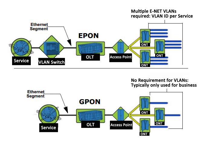
Currently, the passive optical network (PON) is rapidly developing country, for example: EPON (Ethernet Passive Optical Network), GPON (Gigabit Passive Optical Network), GEPON (Gigabit Ethernet Passive Optical Network), APON (ATM Passive Optical Network), BPON (Broadband Passive Optical Network) and other network applications, structured cabling will have a direct impact. Now illustrate EPON/GPON networking mode:

EPON/GPON is mainly composed of OLT (Optical Line Terminal), ODN (Optical Distribution Network) and ONU (Optical Network Unit) and other components. EPON / GPON networking shown in Figure 1:

 EPON / GPON networking

The network characteristics of EPON/GPON:

* On the OLT and ONU in addition to optical interface, combined with GE (Gigabit Ethernet), FE (Fiber optic Ethernet), RF (Radio Frequency), E1 (2.048Mbps) interfaces, can be applied to various network applications.

* EPON can provide uplink and downlink symmetrical rate 1.25Gbps.

* GPON can provides uplink 155Mbps, 622Mbps, 1.24Gbps or 2.48Gbps; Downlink 1.24Gbps or 2.48Gbps.

* Public IP network signal WDM CWDM DWDM, the uplink of 1490nm and downlink of 1310nm signal through the central office OLT integrated transceivers were injected into the same optical fiber, through the optical distribution network ODN spending 32.64 points or 128 optical link to the corresponding ONU. If necessary, can also be injected CATV signals using the third wavelength of 1550nm central office OLT transceiver integrated in the corresponding ONU than the client integrated transceivers separated by the RF interface of the user received a cable distribution network.

* EPON/GPON network support tree, star, bus, hybird and redundant topology etc..

* EPON is based on the standard Ethernet technology and IEEEP802.3ah, in the case of transport 1.25Gbps data stream, the optical line terminal (OLT) and the optical network terminal (ONU) between a transmission distance up to about 20km.

* GPON is based on the ITU-T standard G984.1-G984.5 version, is preferred in Europe and North America, FTTH technology, is being used worldwide. GPON generic framing protocol that provides a multi-protocol transmission efficiency can provide an open interface, with 2.48Gbps rate symmetric and asymmetric transmission capacity, OLT/ONU transmission distance up between 37km.

b. FTTH or FTTB/N

As EPON/GPON technology matures, the price of Optical Fiber Cable are more and more cheap. Fiber optic cable extends to the floor, community nodes, and even to the family increasingly likely. As telecom companies certainly want to consider the relationship between input and output in the short term cost recovery and profit is the ultimate goal.

The advantages of FTTH solutions:

1. Provide greater bandwidth capacity, suitable for high speed network applications.

2. Is not affected by the outside electromagnetic interference, anti-interference performance is good, high quality communications.

3. Silica fiber material production inexhaustible.

4. The price of fiber optic cable has lower than copper (but photoelectric conversion equipment price is still relatively high, therefore, the overall cost is higher).

The disadvantages of FTTH solutions:

1. Same scale projects, the initial investment is higher.

2. New fiber optic cable and more, longer construction period (relative to the FTTB/N solution).

3. Slow return on investment.

WDM Networks: The Transponder

Share

In optical fiber communications, WDM Transponder sends and receives the optical signal from a fiber. A transponder is typically characterized by its data rate and the maximum distance signal travels.

The transponders are of two types namely transmit transponders and receive transponders. The function of transmit transponder is to convert the incoming optical signal into pre-defined optical wavelength. The transponder (transmit) first converts the optical signal to an electrical signal and performs reshaping, retiming and retransmitting functions, also called 3R functions. The electrical signal is then used to drive the laser, which generates the optical signals having optical wavelength. The output from the all transponders (transmits) is fed to combiner in order to
combine all optical channels in optical domain. In receive transponder, reverse process takes place.

Individual wavelengths are first split from the combined optical signal with the help of Optical Splitter and then fed to individual receive transponders, which convert the optical signal to electrical, thus 3R function and finally convert the signal back to the optical. Thus the individual channels are obtained. As the output of the transponder is factory set to a particular wavelength, each optical channel requires unique transponder.

Often, fiber optic transponders are used for testing interoperability and compatibility. Typical tests and measurements include jitter performance, receiver sensitivity as a function of bit error rate (BER), and transmission performance based on path penalty. Some fiber optic transponders are also used to perform transmitter eye measurements.

The transponder according to the invention utilises delays that are switchable between different optical fiber lines, so as to be able to select many different lengths without the necessity of re-designing the same transponder. Moreover, the transponder according to the invention uses a Single Side Band (SSB) optical component which produces an optical shift of the frequency of the radar signal, that avoids the drawbacks and solves the problems of the traditional electrical systems. The transponder according to the invention is comprised in multifunctional radar systems and allows at least three different uses: the first is the systems calibration on the basis of moving targets that are simulated in the production step,the second one is the performances test of a radar that has already been calibrated in the step of the system acceptance by the client (Field Acceptance Test), and the third one is the support to the identification of possible faults and nonworking partsof the radar, during the operation life of the same radar system. The transponder of the invention comes out to be easily producible and transportable.

An integrated transponder will also be needed: one transponder that couples to 10 individual fibers at a much lower cost than 10 individual transponders. With a super-channel transponder, several wavelengths are used, each with its own laser, modulator and detector. Photonic integration is the challenge to achieve a cost-effective transponder.

The Difference Between Fiber Optic Transponder And Fiber Optic Transceiver

A transponder and transceiver are both functionally similar devices that convert a full-duplex electrical signal in a full-duplex optical signal. The difference between the two is that fiber transceivers interface electrically with the host system using a serial interface, whereas transponders use a parallel interface. So transponders are easier to handle lower-rate parallel signals, but are bulkier and consume more power than transceivers.

The Application of 10G PON Technology

Share
With the major carriers “Broadband speed”, “Light of Copper” project extensively, The future will be a multimedia broadband services, video on demand, interactive games as the main feature, high-bandwidth, integrated operators will be judged promoted by the merits of the standard broadband products.
Under the broadband Fiber Optic Network in the trend, PON technology has become the world’s attention to various telecom operators hot technology is one of the operators to implement “broadband speed”, “Light of Copper” engineering technology base. Wheter EPON, or GPON, which provides only for the uplink and downlink bandwidth of 1G or 2G, but with the current interactive network TV (IPTV), high definition television (HDTV), online games, video services and other large flow, a large broadband business development and popularization of the per-user bandwidth demand is expected to grow every three years, a trend of increasing magnitude, from the future operator of long-term trends, per-user bandwidth demand will be 50-100 Mbit/s between. This way, EPON and GPON are unable to meet the future needs of the development of broadband services, the existing PON port bandwidth, there will be a bottleneck. Therefore, ITU-T, FSAN, IEEE and other major standards organizations begin the next generation of PON technology research.
Similar to 1G PON Technology, 10G PON and 10G EPON technology is still divided into two camps 10G GPON. In IEEE 802.3av 10G EPON standards, maximizing follows the usual IEEE 802.3ah content, with good upward compatibility.
>> 10G PON technical analysis
Recalling the history of PON technology can be found in each of the PON technology from birth to the end of the day have to go through large-scale commercial development of technical standards, the relevant chip and optical module development, test and production, the creation of experimental and commercial bureau 4 stages of deployment, which lasted five years or so, each one of which will go through several stages of development of the argument.
* Standardization Advances
Standards are mature is the precondition of judging whether a technology have lead to condition. At this stage, including IEEE, ITU-T, FSAN and number of ongoing international standardization organizations 10G EPON and 10G GPON standards development work of two technologies. Overall, the 10G EPON technology start time earlier than 10G GPON, therefore, the current standardization process of 10G EPON slightly faster than 10G GPON.
a. 10G EPON
Technologies with 1G EPON, 10G EPON standards are mainly led by the IEEE to complete. IEEE organization at September 12, 2009 released the 10G EPON international standards 802.3av, this standard focuses on the physical layer 10G EPON technology research, followed the tradition of 1G EPON MPCP protocol, the 1G EPON downlink bandwidth increases to 10G at the same time, to ensure that the operator of the original investment is not compromised and 10G EPON smooth upgrade, IEEE 802.3av standard defines and 1G EPON ONU coexist in the same ODN network of 10G EPON ONU standard parameters.
Further, in IEEE 802.3av standard, the physical layer defines two parameters: one asymmetric model, which 10G rate downlink and 1G rate uplink; other is symmetrical pattern, i.e. uplink rate and downlink rate are both 10G. Asymmetric mode can be considered as a transitional form symmetrical patterns, in the early less demand for upstream bandwidth and cost sensitive applications, you can use an asymmetric form. With the development of business and technology progress, will be gradually transition to a symmetrical mode.
b. 10G GPON
According to ITU-T Study plans, NGPON will experience two standard phases: the first phase is the coexistence with GPON, GPON ODN heavy use of XG-PON, which in turn contains the uplink and downlink phase XG-PON1 asymmetric and symmetric XG-PON2 two kind of model; Second stage is completely new ODN’s NGA2. High concern Wavelength Division Multiplexing – Passive Optical Network (WDM-PON) technology areas belong to the second stage, it was adopted in a fiber access network using multiple wavelengths to achieve the expansion, but the burst mode CWDM, colorless ONU transceivers, tunable WDM devices and some difficult technology can not break, WDM-PON is still at the proof stage.
In the end of September 2009 meeting of the ITU-T SG 15 plenary session, Q2 Working Group officially launched the NG-PON standard text in the first stage, that overall demand for next-generation PON systems (G.987.1) and Physical Layer Specifications (G.987.2), and also developed in mid-2010, publishing transmission convergence layer (G.987.3) and management control interface (G.988) standards program.
* Technical Parameters
Wheter IEEE 802.3av, or ITU-T G.987 protocol suite, all relevant technical parameters for 10G PON physical layer index, optical power budget to make a detailed definition. However, due to the two major standards organizations considered the starting point, the technical indicators are also some differences.
a. 10G EPON
There are four key points of 10G EPON technology:
1. Defines six 10G EPON optical power budget, in view of the asymmetric mode PRX10, PRX20 and PRX30 as well as for symmetric mode PR10, PR20 and PR30, these six kinds of optical power budget model is basically to meet the construction needs of the service provider network;
2. 10G EPON technology in achieving the 1G EPON conventional multi-point control protocol layer (MPCP) based on the forward compatibility, also extended the original message type, for reporting optical terminal equipment (OLT), ONU Optical Transceiver switch time to meet the 10G EPON system requirements;
3. 10G EPON uses (255, 223) Forward Error Correction (FEC) encoding method, the encoded with FEC coding for the same strain of 1G EPON, but its strong support 10G EPON coding gain can lower the sensitivity of the optical receiver;
4. 10G EPON uplink and downlink wavelength for the re-planning, downlink using 1268-1280nm wavelength, then reuse the original uplink of 1G EPON 1575-1580 nm wavelength, the wavelength in order to avoid conflicts, 10G EPON uplink only use time division multiple access (TDMA) manner.
b. 10G GPON
Has been released G.987.1 standard that defines 10G GPON system’s overall technical requirements and system architecture, clearly put forward the 10G GPON system to ensure good QoS, based on the traditional telecom services to fully support all emerging businesses and the same time, also provides dynamic Bandwidth Allocation (DBA) algorithm, energy saving, authentication and encryption related content to inherit the original 1G GPON technology; The G.987.2 is the focus of standardized 10G GPON physical layer parameters, including downlink rate, ODN power budget, splitting ratio, up and down the line wavelength range and line coding, etc., although down the line of 10G EPON same wavelength range and 10G EPON, GPON but due to the wavelength with 1G is not conflict, therefore, 10G GPON uplink and downlink are used wavelength division multiple access (WDMA) manner.
* Industrial chain development
A complete industrial chain, including chip PON, optical modules and equipment three links. If to analysis PON industry chain, it need to start from the three links, analysis of every link current development status and future development trend.
Overall, 10G EPON and 10G GPON is currently not reach the requirements of large-scale commercial applications, although some equipment manufacturers have recently introduced a 10G EPON or 10G GPON products, and with operators, the creation of some experimental inning, but still in the laboratory testing phase, is still some distance away from the large-scale commercial.
>> Conclusion

10G PON technology to meet future access networks, “large-capacity, fewer offices,” the direction of development, while improving access speed, supports larger branching ratio, covering more users. Therefore, 10G PON technology will become the future telecom operators to achieve “broadband speed”, “Light of Copper” and other broadband network construction hot technology for sustainable development.

110 Punch Down Block Wiring System

Share

Punch down block, also referred to as a cross-connect block, terminating block, or a connecting block, is a device that connects one group of wires to another group of wires through a system of metal pegs that the wires are attached to, often used in telecommunications closets that support LAN(Local Area Network). Punch down blocks are the predecessors to patch panels and were commonly used to support low-bandwidth Ethernet and token-ring networks.

There are two styles of punch down blocks available for telephony, the 66 block and the 110 block, these blocks are used to connect station cabling to the trunk cabling that goes from an IDF to the MDF.

110 Punch Down Block

A 110 blocks is a updated version of punch down block, is the core part of the connection management system, used to connect wiring for telephone systems, data network wiring, and other low-voltage wiring applications. 110 type wiring block is flame retardant, injection-molded plastic to do the basic devices and the termination cabling system is connecting on it.

The 110 block is designed for 22 through 26 gauge solid wire. This is the termination used on Cat 5e Patch Panels, cat 6 patch panel and RJ-45 jacks. They are also formed into block type terminations the size of small 66 blocks. The 110 block is designed for 500 MHz (1 gb/s) or greater bandwidth. 110 blocks are acceptable for use with AES/EBU digital audio at sample rates greater than 268 KHz as well as gigabit networks and analog audio.

The specifications of 110 Connecting Blocks are as follows: 25 pairs 110 type wiring block, 50 pairs 110 type wiring block, 110 pairs 110 type wiring block, 300 pairs 110 type wiring block. The distribution frame package of 110 type wiring blocks should also include 4 or 5 blocks, connection block, blank labels and tags folder and the base. 110 type wiring block system uses easy quick-fit plug-hop loops which can be simply rearranged, so it provides a convenient cross-connect to non-professional and technical personnel management system.

110 Punch Down Tool

A Punch Down Tools is used to force solid wire into metal slots on the 110 block. Present residences typically have phone lines entering the house to a sole 110 block, and then it is spread by on-premises wiring to outlet boxes all over the house in a star topology.

Both styles of punch block use a punch down tool to terminate the wires to the block. To terminate a wire, you place it into the terminal and then push it down to make contact with the punch down tool. The punch down tool fits around a 66 block terminal or into a 110 block terminal. One side of the blade is sharp to cut the wire off flush, this is normally marked on the tool with the word cut. Be sure to have this side oriented to cut off the loose end of the wire and not the end going to the other block. Hide extra cable behind the block in case you ever have to reterminate a pair so that you don’t have to reterminate the entire cable.

Whatever the dimensions of the punch down tools are, usage is the same. Many tools have a dual blade that can be flipped depending on which style of block is in use.

How To Purchase Twisted Pair Cable

Share

In its simplest form, twisted pair cable consists of two insulated strands of copper wire twisted around each other. There are two types of twisted-pair cable: unshielded twisted-pair (UTP) and shielded twisted-pair (STP) cable. A number of twisted-pair wires are often grouped together and enclosed in a protective sheath to form a cable. The total number of pairs in a cable varies. The twisting cancels out electrical noise from adjacent pairs and from other sources such as motors, relays, and transformers.

Category 5e or Category 6 Twisted Pair Cable

Currently there is a great deal of confusion among Ethernet cable buyers concerning whether to purchase Cat5e, or to use Cat6. Most of this confusion comes from a misunderstanding by the buyer that buying Cat6 cable will give them an “all gigabit” network. This is not the case. Unless every single component in the network is gigabit rated, then you will never have a gigabit network, because your network will always run at the speed of your slowest device.

Cat5e cable of good quality can run near or at gigabit speeds, it just cannot be “certified” for this use. By comparison, Cat6 is designed especially for gigabit use, and is certified to operate at said speed. It becomes a matter of whether or not you want to pay all that extra money, for little or no noticeable improvement in the performance of you network.

In most cases, it makes more sense to go with Cat5e. It is for this reason that most of your new installations in the private sector are going with Cat5e. It is more economical, performs well, and is readily available in many colors. Many IT professionals when asked about why they specified Cat6 for a specific job, often responded stated that they “wanted the best they could get.” This is the line of thought behind many purchases of cable.

The average consumer often times is not aware that there is no real benefit to them to use Cat6, so they let someone talk them in to buying it. FS.COM is committed to helping people make good decisions about cable purchases and we are always standing by to help you.

Fs twisted pair cable.jpg

How to Buy Twisted Pair Cable

Following are some advice you can take when choose a twisted pair cable for your network.

See Packing and Printing Quality

Carefully check the cable box to see whether packing is in good conditions. The packaging of fake cable is usually very poor, so the quality of the external packaging can determine the user’s first feeling. However, good quality cables are usually perfectly packaged. And many manufacturers still paste anti-fake label on the product packaging.

See Identifications on Cable’s Outer Layer

Twisted pair cable insulation outer layer shall be printed with the words such as manufacturers, place of origin, performance standards, product categories (Cat5e Ca6t, etc.) and cable length identification.

See Twisting Density

In order to reduce signal interference, each line pairs of the twisted pair cable are twisted in a counterclockwise direction to each other and the different line pairs of the same twisted pair cable also has different twisting density. If the twisting density does not meet the technical requirements, serious near-end crosstalk may appear due to the mismatch of the cable resistance, which will shorten transmission distance and reduce the transmission rate. Don’t choose twisted pair cables whose twisting density is incompetent.

See Cable Colors

After peeling the outer layer of twisted pair cable, you can see each pair of wires in a twisted-pair cable is one of four colors: orange, green, blue, or brown. The two wires that make up each pair are complementary. It should be noted that these colors are not dyed on the cable. Don’t choose cables whose color is not clear.

See Flame Retardants Cases

In order to avoid cable’s burning and damage caused by high temperature or fire, the outer layer of the twisted pair cable should have a very good tensile property and flame retardant property. The outer layer of a good twisted pair cable may be gradually melted and misshapen, but won’t burn itself.

Touch the Cable’s Outer Layer

In most cases, we can make an initial judgment by touching the outer layer of twisted pair cable. In order to save cost, bad cable usually uses terrible wire materials. So when we touch it, we may feel sticky and coarsened. However, a good twisted pair cable may feel smooth. Besides, considering that the cable may need to be curved, good cables usually have excellent extensibility. Therefore, good cables may feel full.

Conclusion

Taking the future applications into consideration, we should install the most advanced cabling products, because the cable is often difficult to re-install and replace. Then, you should use cat6 cables instead of cat 5e cable. Though cat 6 cable is a little expensive than cat 5e cable, in order to reduce cost for network upgrade in the future, cat 6 cables are still worth considering.

Related Articles:
Ethernet Cable Types – Cat5e, Cat6, Cat6a, and Cat7
Difference of Straight Through and Crossover Cable
Patch Cable vs. Crossover Cable: What Is the Difference?
Quick View of Ethernet Cables Cat5, Cat5e And Cat6